System and Method of Use for Composite Floor

Inactive Publication Date: 2011-05-19
NEW JERSEY INSTITUTE OF TECHNOLOGY
View PDF65 Cites 12 Cited by
  • Summary
  • Abstract
  • Description
  • Claims
  • Application Information

AI Technical Summary

Benefits of technology

[0009]A composite floor system and method of construction thereof are herein described. The method and system described herein may allow components of the system to be assembled prior to delivery to the work site. Thus, the design of the composite floor system may facilitate a reduced assembly time on-site

Problems solved by technology

Traditional composite floor systems require decking which is often limited to one particular type.
Further, many currently available floor systems use discontinuous slabs of concrete due to design constraints.
In addition, traditional composite floor systems ge

Method used


Image

  • System and Method of Use for Composite Floor
  • System and Method of Use for Composite Floor
  • System and Method of Use for Composite Floor

Examples


Example

[0046]A composite floor system may include two or more components to allow for transfer of shear forces between the component parts. In some embodiments, multiple components may act as a unified object. Components used in the composite floor system may include lightweight materials, to decrease a total weight of the system while maintaining the strength and durability of the floor system.

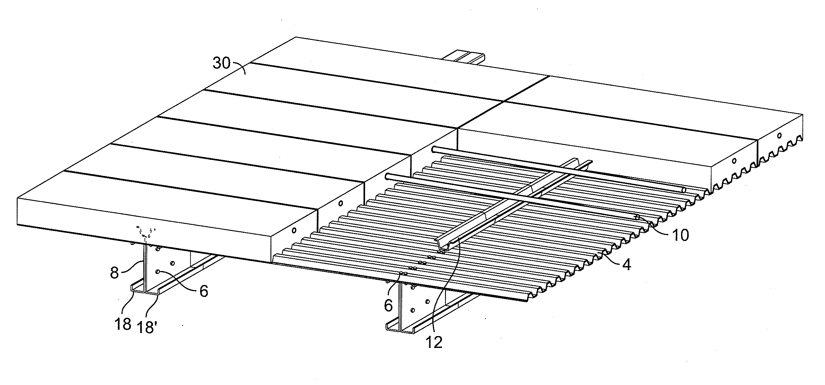
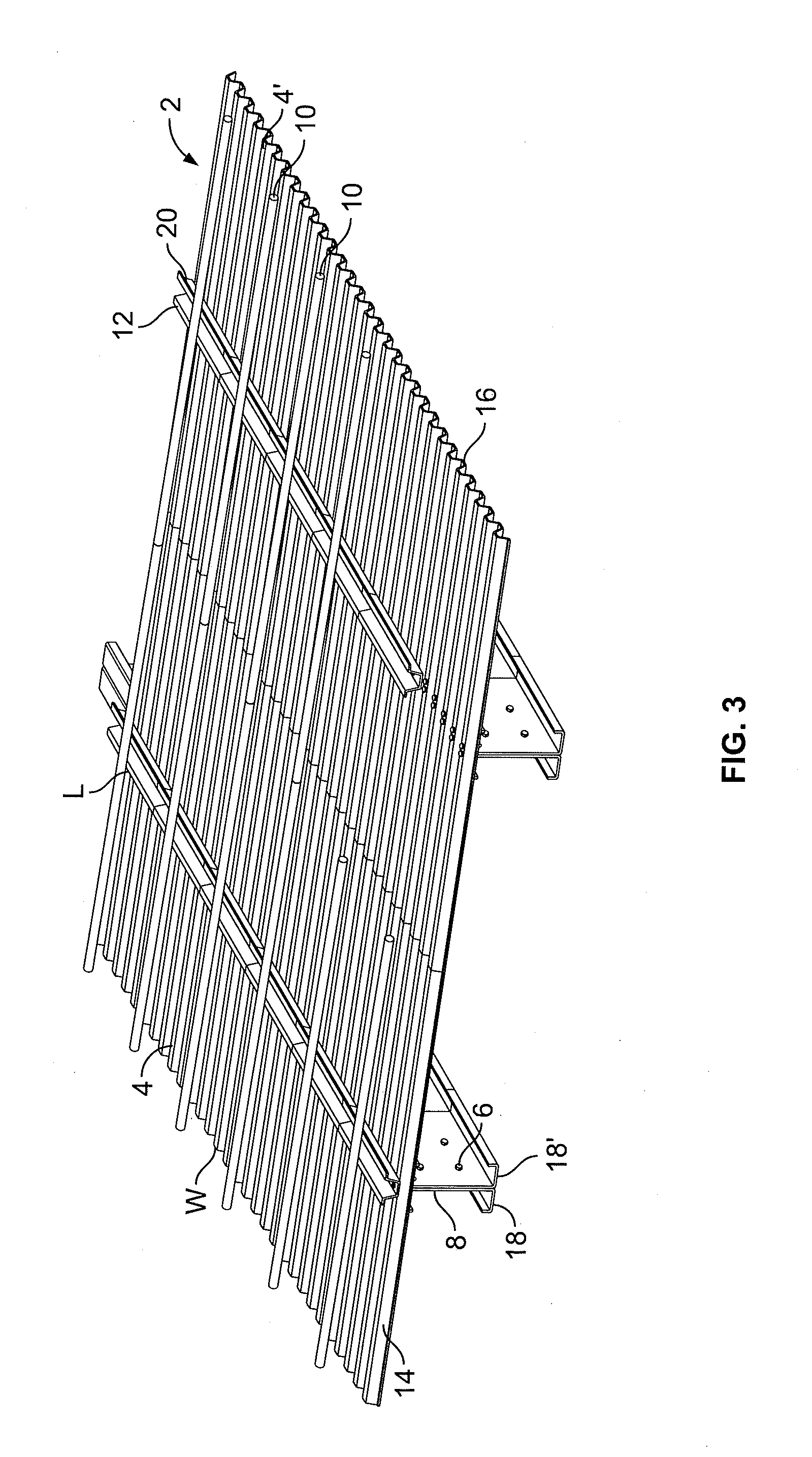
[0047]FIG. 3 depicts an embodiment of composite floor system 2 prior to the addition of a slab. In this embodiment, composite floor system 2 includes decking material 4, 4′ fasteners 6, support members 8, reinforcing members 10, transfer members 12, and a slab (not shown).

[0048]Decking material 4 may include various materials including, but not limited to wood, plywood, fiberboard, metal, corrugated sheet metal, sheet metal (e.g. cold form steel), pre-cast concrete materials, gypsum, GYP-CRETE® underlayment, gypsum-metal composites, backer boards, rubber padding, fiberglass, polymer sheets, foam-cor...


PUM


Abstract

A system and method of constructing a composite floor system having increased shear transfer between a slab and support members of the system is described. The composite floor system may include any combination of the following elements: a support member, a reinforcing member, a transfer member, a decking material, a fastener, and/or a slab. The transfer member may be connected to the support member.

Description

CROSS-REFERENCE TO RELATED APPLICATIONS[0001]This is a continuation-in-part of U.S. patent application Ser. No. 11 / 820,250, filed Jun. 19, 2007, which claims the benefit of U.S. Provisional Patent Application No. 60 / 815,340, filed Jun. 20, 2006, the disclosures of which applications are incorporated herein by reference in their entireties.TECHNICAL FIELD[0002]The present disclosure relates to the field of composite floor systems. More particularly, the present disclosure refers to systems and methods of constructing a composite floor system having increased shear transfer between a slab and support members of the system. Further, some embodiments of the systems and methods herein described may allow for increased load carrying capacity, increased resistance to deflection, increased ductility and / or increased potential energy absorption. In an exemplary embodiment, the disclosed system may reduce a weight of the system while maintaining strength and ductility of the composite floor s...

Claims


Application Information

Patent Timeline
IPC IPC(8): E04B5/18E04B5/38E04B5/00
CPCE04B5/40E04B5/43E04C3/291E04C2003/0465E04C2003/0413E04C2003/043E04C3/294
Inventor HSU, CHENG-TZU THOMASPUNURAI, SUNMUNOZ, PEDRO R.
Owner NEW JERSEY INSTITUTE OF TECHNOLOGY
Why Eureka
Try Eureka