Oceanic Wave Energy Utilization System

Active Publication Date: 2011-05-19
ZHANG YI +4
View PDF7 Cites 15 Cited by
  • Summary
  • Abstract
  • Description
  • Claims
  • Application Information

AI Technical Summary

Benefits of technology

[0032]The present invention is simple and reliable in structure, low in cost, adaptable to the disordered change in oceanic wave, less in intermediate links of energy conversion, high in energy conversion efficiency, stable and persistent in output

Problems solved by technology

As a result, very little tidal energy is used in power generation.
As a result, the oceanic wave energy is the most abundant, inexhaustible, polar and reliable energy resources in the earth, while wave energy also accounts for major weight in ocean energy sources.
It is difficult for other types of mechanical energy conversion devices to achieve continuous, stable, concentrated and controllable energy with even rate, so that they are less applied.
Although three types of wave power generation devices have their respective advantages, they have common disadvantages as follows: 1. Multiple intermediate links for converting oceanic wave energy to electric energy, complex equipment, low efficiency, not easy to form large-scale power generation; 2. Only one-dimension energy in the mechanical energy of oceanic wave can be partially utilized, and it is impossible to absorber the disordered,

Method used


Image

  • Oceanic Wave Energy Utilization System
  • Oceanic Wave Energy Utilization System
  • Oceanic Wave Energy Utilization System

Examples


embodiment 1

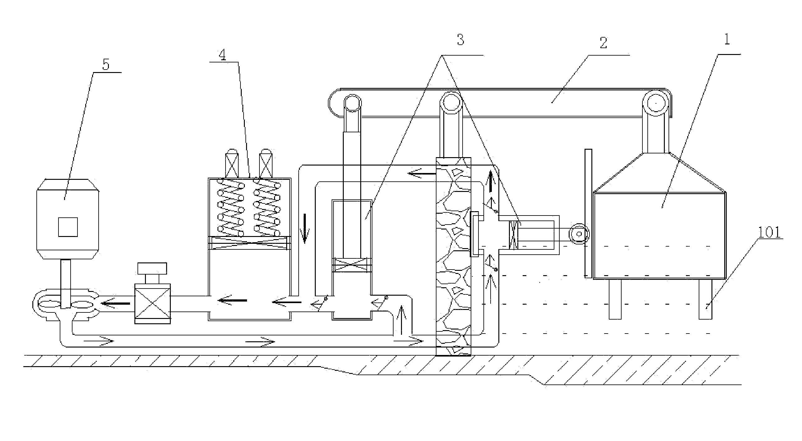
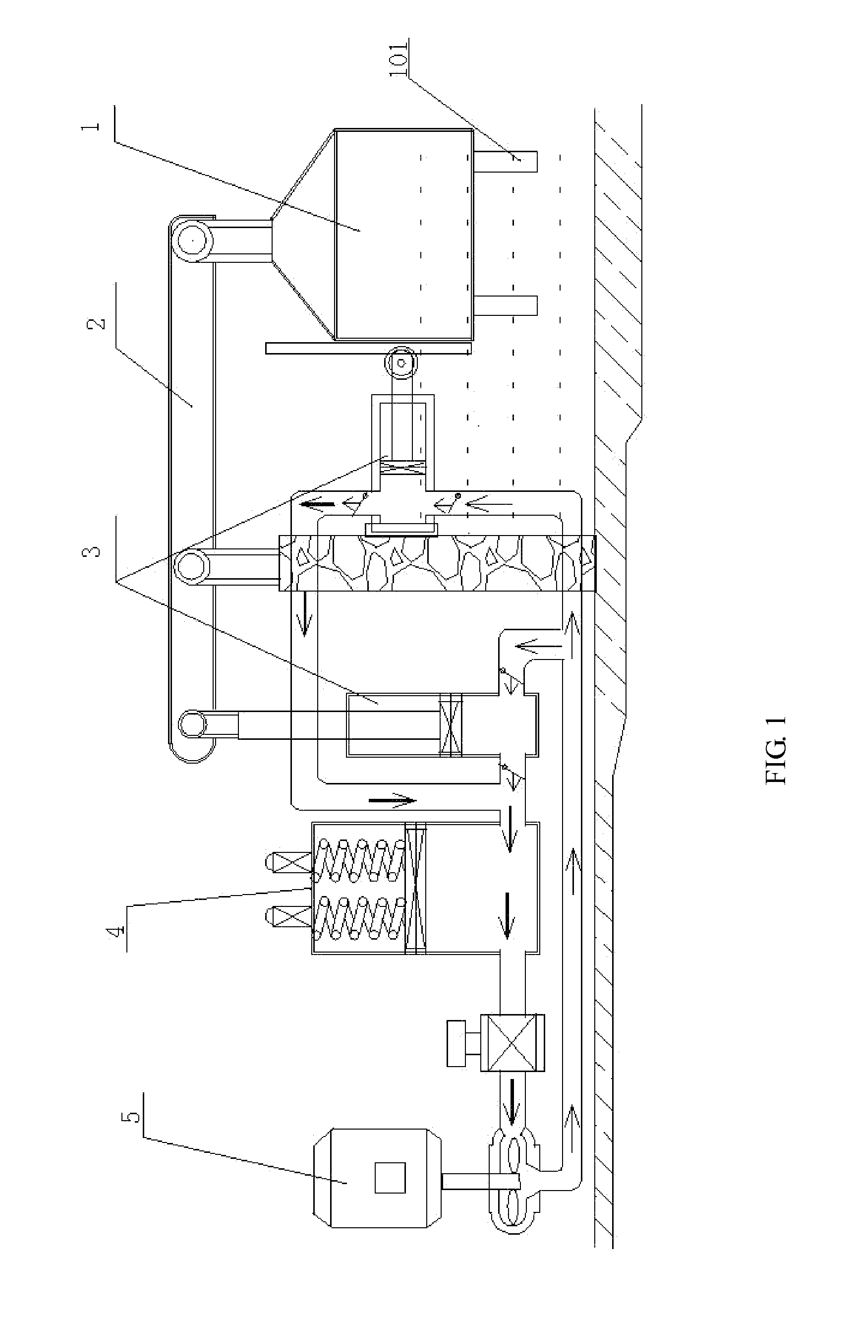
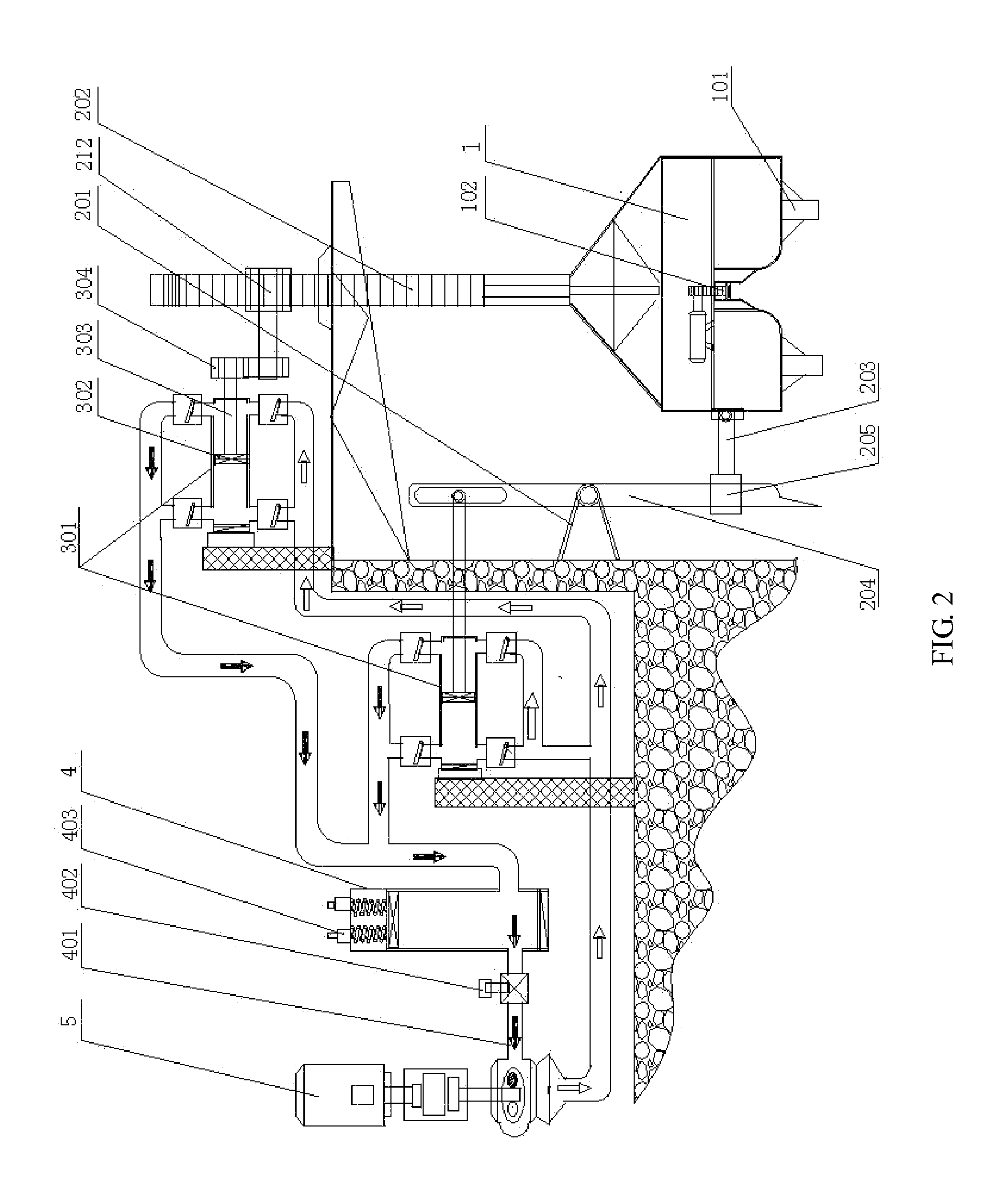
[0053]As shown in FIG. 2, the floating energy collection device 1 is connected with the energy transfer device 2 which is fixed at shore side; the floating energy collection device 1 is a hull-shaped solid float placed in the sea, its long axis is in parallel with the seashore, its offshore distance exceeds half meter, its water depth is required to exceed 3 meters, its draft is more than 1 meter; energy collection plate 101, which is perpendicular to the sea level and is in parallel with the shore line, is set at the bottom of the floating energy collection device; several funnel-shaped vertical wave energy collection devices with big openings facing downward, which are communicated with seawater, are also set at the bottom of the floating energy collection device, the tail of each vertical wave energy collection device is a hydraulic piston cylinder, which can receive the energy generated from the up and down movement of wave and realize energy conversion. To prevent the damages c...

embodiment 2

[0064]As shown in FIG. 5, when the floating energy collection device 1 is connected to the energy transfer device 2 fixed at shore side, the floating energy collection device 1 is a solid float with specific weight less than sea water, it is preferred that the floating energy collection device 1 is designed as elongated floater with “n” or “T” shaped-section, so that it is floated on water surface, with a small fraction emerging from water. The material for manufacturing the horizontal floating surface of the solid floater can be made up of several used motor tyres, which are connected together. The seawater pushing stress surface(s) of the solid floater may be a surface or two parallel surfaces, which are vertically arranged along the elongated long axis and composed of sea-water corrosion resisting materials, such as ceramic, tempered glass, fiber glass, plastic, non-corrosive metal and treated timber. The floating energy collection device is so designed to adapt to the fluctuatio...

embodiment 3

[0073]As shown in FIG. 8, when the fixed seat 1 in the energy transfer device 2 is fixed at sea bottom, a vertical through hole is set on the center of the floating energy collection device 1, the energy transfer rod is a swaying pillar 216, with ring tooth 217 being set on its surface, the swaying pillar 216 is set in the through hole of the floating energy collection device 1, the lower end of the swaying pillar is connected with the universal shaft of the fixed seat 201 at sea bottom, so that the swaying pillar sways with the swaying of the floater to prevent the pillar from fracture; several elastic elements are set at the lower part of the swaying pillar where is closed to the fixed seat 201, one end of each elastic element is immovably connected with the swaying pillar, and another end of each elastic element is immovably connected with the fixed seat; the elastic elements have holding action for the swaying pillar, so that the swaying pillar can only sway within certain range...


PUM


Abstract

An oceanic wave energy utilization system includes a floating energy collection device (1), an energy transfer device (2) and an energy conversion device (4). The floating energy collection device is connected to the energy conversion device via the energy transfer device. The floating energy collection device is made up of a hull-shaped float and a float limitation device. Vertical energy collection plates (101) are arranged at the underside of the float, while the energy transfer device is made up of a fixed seat and an energy transfer rod, said fixed seat being fixed at shore-side or at the seabed and movably connected to the energy transfer rod. The energy transfer rod is movably connected to the floating energy collection device and to the energy conversion device.

Description

TECHNICAL FIELD[0001]The present invention relates to the technical field of energy conversion, in particular to an oceanic wave energy utilization system.BACKGROUND OF THE INVENTION[0002]The ocean covers more than 70% of earth surface. Under different moon's gravities during different time periods, the sea water in the ocean produces rising tide and falling tide twice from day to day, with tidal difference ranging from 2-6 meter and even more than 10 meters. In addition, varying fluctuation wave is also produced. Such tide and wave can generate tremendous energy.[0003]In the tidal power generation of the prior art, shrinkage water channel is utilized to introduce the oceanic wave on the tide to the elevated reservoir to form head of water (water head), and the down flow of water head is utilized to directly drive the water-turbine generator set to generate power. As a result, very little tidal energy is used in power generation.[0004]Wind wave can be generated when wind acting on s...

Claims


Application Information

Patent Timeline
IPC IPC(8): F03B13/18
CPCF03B13/1815F03B13/186F03B13/187F03B13/182F05B2260/50Y02E10/38F05B2260/4031Y02E10/30
Inventor ZHANG, YIZHANG, JILINZHANG, HUIJIEZHUO, XIAOQINLIU, FENG
Owner ZHANG YI
Why Eureka
Try Eureka