Leak detector and method of detecting leak

Inactive Publication Date: 2011-05-19
ULVAC INC
View PDF7 Cites 20 Cited by
  • Summary
  • Abstract
  • Description
  • Claims
  • Application Information

AI Technical Summary

Benefits of technology

[0009]In view of the above-described problem, this invention has a problem of providing a leak detector

Problems solved by technology

As a result, there is a disadvantage in that much time is required before the leak test can be started.Patent document 1: JP-A-1998-38746.
Outside t

Method used


Image

  • Leak detector and method of detecting leak
  • Leak detector and method of detecting leak
  • Leak detector and method of detecting leak

Examples


Embodiment Construction

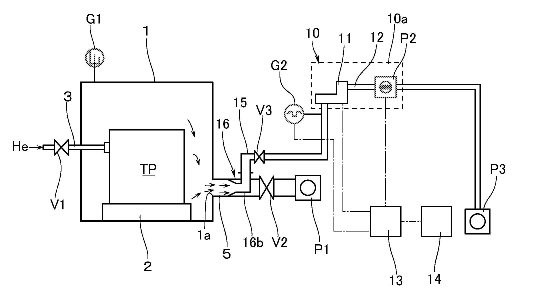
[0020]With reference to the accompanying drawings, a description will now be made of an embodiment of a leak detector according to this invention. In this embodiment, a hermetically sealed vessel such as a tank and the like is defined as a test piece TP. This test piece TP is subjected to a leak test by disposing it inside a test chamber (vacuum chamber) in which a vacuum atmosphere can be formed.

[0021]With reference to FIG. 1, reference numeral 1 denotes a test chamber (vacuum chamber) in which a leak test is performed. The test chamber 1 has a predetermined volume and is provided, at the bottom thereof, with a supporting base 2 which holds thereon the test piece TP. On a side surface of the test chamber 1 there is disposed by insertion a flexible pipe 3 through a vacuum seal such as an O-ring and the like (not illustrated). That end of the pipe 3 which lies inside the test chamber 1 is connected, through a flange with an O-ring (not illustrated), to the test piece TP held on the s...


PUM


Abstract

A leak detector detects the presence or absence of a trace amount of leak from a test piece by using helium gas. The leak detector has a guide pipe and a mass spectrometer. The guide pipe is disposed by insertion into an evacuation pipe which is communicated from a vacuum chamber, in which the test piece is disposed, to a vacuum pump. The guide pipe includes an opening portion which opens in a line of flow inside the evacuation pipe. The mass spectrometer for detecting helium is connected to the guide pipe through a gate valve.

Description

[0001]This application claims the priority benefit under 35 U.S.C. §119 of Japanese Patent Application No. 2009-264064 filed on Nov. 19, 2009, which is hereby incorporated in its entirety by reference.BACKGROUND[0002]1. Technical Field[0003]The present invention relates to a leak detector to be used in detecting the presence or absence of a leak in a test piece such as a hermetically sealed vessel, pipe, valve, and the like, and also relates to a method of detecting a leak.[0004]2. Related Art[0005]It has been known to use a leak detector in a leak test (leak detecting method) to detect (or inspect) the presence or absence of a trace amount of leak from a test piece such as a hermetically sealed vessel, pipe, valve, and the like (see, e.g., patent document 1). The leak detector is provided with a mass spectrometer which is arranged: to ionize the gas molecules in the vacuum; and to select only the helium ions to cause them to be incident on an ion collector, thereby quantitatively d...

Claims


Application Information

Patent Timeline
IPC IPC(8): G01M3/20
CPCG01M3/229G01M3/205G01M3/04
Inventor MAEHIRA, TAKAYUKIWAKAMATSU, RYUICHISATO, EIICHI
Owner ULVAC INC
Why Eureka
Try Eureka