Spiral type membrane filtering device and mounting member, and membrane filtering device managing system and membrane filtering device managing method using the same

Inactive Publication Date: 2011-05-19
NITTO DENKO CORP
View PDF25 Cites 13 Cited by
  • Summary
  • Abstract
  • Description
  • Claims
  • Application Information

AI Technical Summary

Benefits of technology

[0056]According to the present invention, the sensor or the power generating section is provided in a mounting member that is attachable and detachable to a spiral type membrane element. Therefore, even if the spiral type membrane element is to be replaced, the sensor or the power generating section can be reused by re-mounting the mounting member t

Problems solved by technology

However, when the management of processing characteristics is carried out train by train as described above, it is difficult to specify the location of an inconvenience when the inconvenience occurs in the membrane element or the connecting section of only a part of the membrane filtering devices among the numerous membrane filtering devices that are held by a train, thereby raising a problem in that a lot of labor will be required in the specifying wo

Method used


Image

  • Spiral type membrane filtering device and mounting member, and membrane filtering device managing system and membrane filtering device managing method using the same
  • Spiral type membrane filtering device and mounting member, and membrane filtering device managing system and membrane filtering device managing method using the same
  • Spiral type membrane filtering device and mounting member, and membrane filtering device managing system and membrane filtering device managing method using the same

Examples


first embodiment

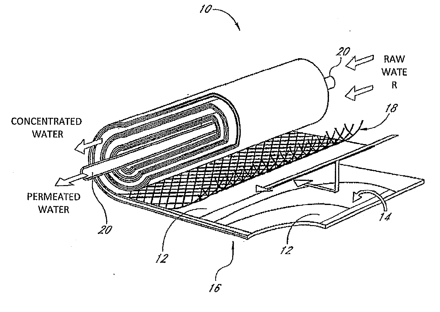
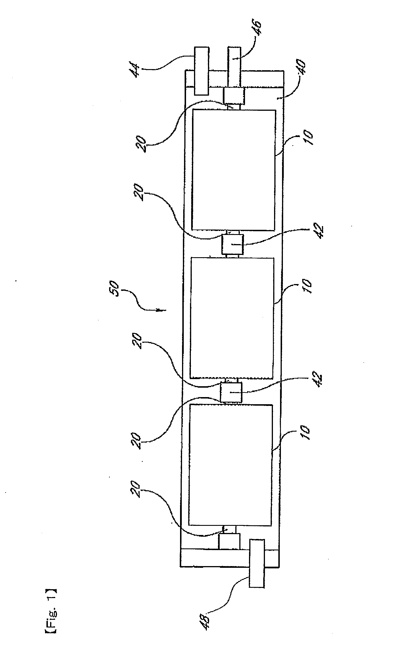
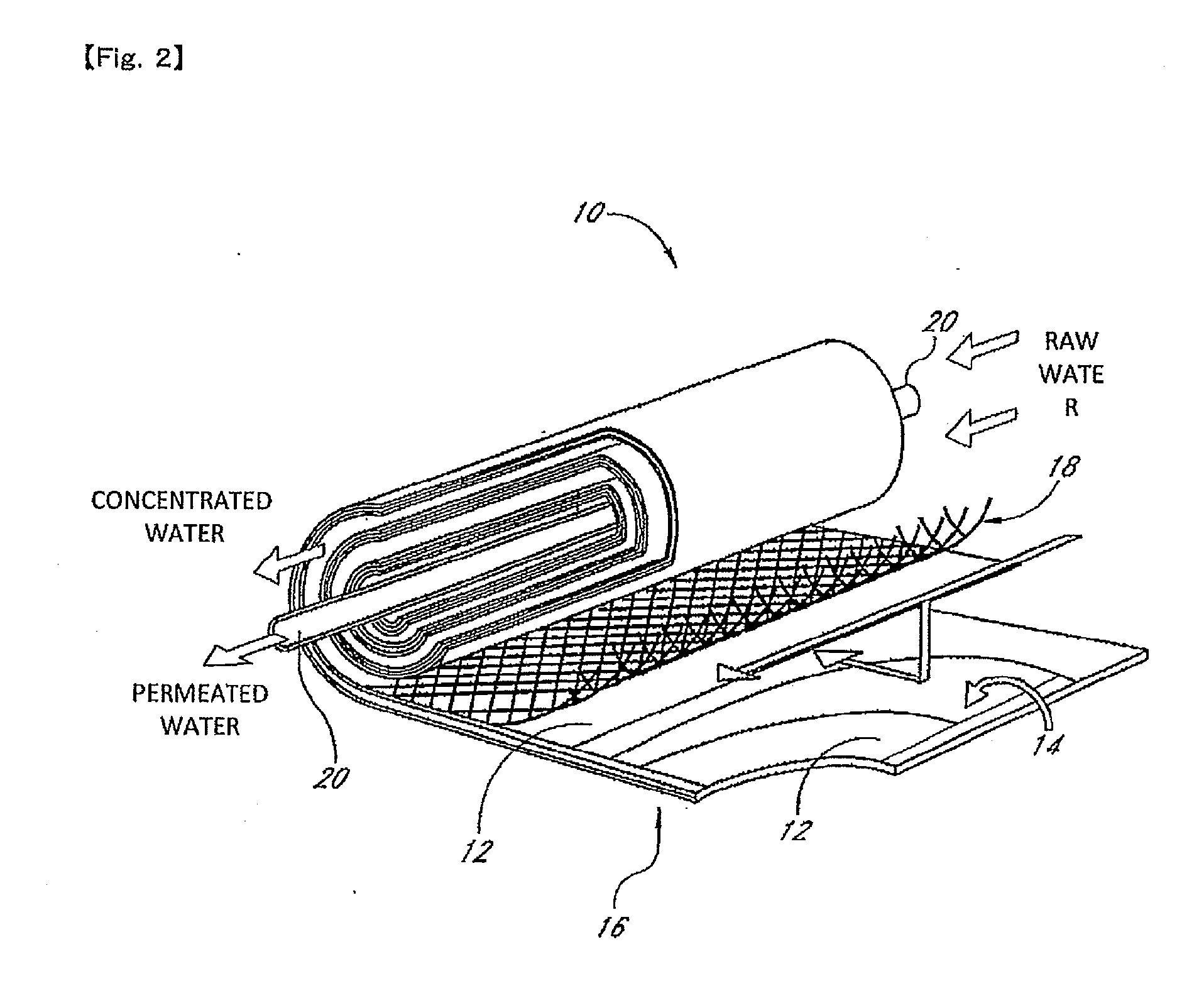
[0095]FIG. 1 is a schematic cross-sectional view illustrating one example of a spiral type membrane filtering device 50 according to a first embodiment of the present invention. Also, FIG. 2 is a perspective view illustrating an internal construction of a spiral type membrane element 10 of FIG. 1. This spiral type membrane filtering device 50 (hereinafter simply referred to as the “membrane filtering device 50”) is constructed by arranging a plurality of spiral type membrane elements (hereinafter simply referred to as the “membrane elements 10”) in a line within an outer vessel 40.

[0096]The outer vessel 40 is a tube body made of resin, which is referred to as a pressure-resistant vessel, and is formed, for example, with FRP (Fiberglass Reinforced Plastics). A raw water flow inlet 48 through which a raw water (raw liquid) such as waste water or sea water flows in is formed at one end of the outer vessel 40, and the raw water that flows in through the raw water flow inlet 48 is filter...

second embodiment

[0116]In the first embodiment, description has been given of a construction in which power generation is carried out based on the rotation of the rotor (blade wheel 21) provided in the interconnector 42. In contract, the second embodiment is different from the first embodiment in that the rotor is provided outside of the interconnector 42.

[0117]FIG. 5 is a schematic perspective view illustrating one example of an internal construction of a spiral type membrane element 10 in a spiral type membrane filtering device 50 according to the second embodiment of the present invention, showing a state in which the internal construction is seen through. In this example, a space 27 is formed between the end surfaces of the membrane elements 10 that are positioned on the two sides with the interconnector 42 sandwiched therebetween. This space 27 is a region through which the raw water flowing from the raw water flow path 28 formed by the supply side flow path material 18 within one membrane elem...


PUM

PropertyMeasurementUnit
Pressureaaaaaaaaaa
Poweraaaaaaaaaa
Flow rateaaaaaaaaaa

Abstract

Provided are a spiral type membrane filtering device by which an electric component can be re-used and a mounting member, as well as a membrane filtering device managing system and a membrane filtering device managing method using the same. An interconnector (42) attachable and detachable to a membrane element is provided with a sensor that detects the property of liquid such as raw water or permeated water that flows within a membrane filtering device, or a power generating section (26). Therefore, even if the membrane element is to be replaced, the sensor or the power generating section (26) can be re-used by re-mounting the interconnector 42 onto a new membrane element. Also, since there is no need to add a change to the membrane element, a conventional membrane element can be used as it is.

Description

TECHNICAL FIELD[0001]The present invention relates to a spiral type membrane filtering device equipped with a spiral type membrane element in which a separation membrane, a supply side flow path material, and a permeation side flow path material in a laminated state are wound in a spiral form around a central pipe, and a permeated liquid that is filtered by the separation membrane from a raw liquid supplied via a raw liquid flow path formed by the supply side flow path material is guided to the central pipe via the permeation side flow path material, and to a mounting member as well as to a membrane filtering device managing system and a membrane filtering device managing method using the same.BACKGROUND ART[0002]A spiral type membrane filtering device (hereinafter simply referred to as the “membrane filtering device” is known that is constructed by plurally arranging the aforesaid spiral type membrane element (hereinafter simply referred to as the “membrane element”) in a line and ...

Claims


Application Information

Patent Timeline
IPC IPC(8): B01D63/10B01D61/20C02F1/44
CPCB01D61/025F05B2220/20B01D63/12B01D65/02B01D65/10B01D2311/13B01D2313/246B01D2313/90B01D2321/162B01D2321/164C02F1/44C02F1/441C02F2209/008C02F2209/02C02F2209/03C02F2209/05C02F2209/11C02F2209/40F03B13/00B01D61/12
Inventor KONISHI, TAKAHISAMARUYAMA, KOUJIKOUNO, TOSHIKIHIRANO, KEISUKEOOTANI, AKIRAYOSHIKAWA, HIROSHIIKEYAMA, NORIO
Owner NITTO DENKO CORP
Why Eureka
Try Eureka