Digital slope compensation for current mode control

Active Publication Date: 2011-05-19
DELTA ELECTRONICS (THAILAND) PUBLIC CO LTD
View PDF7 Cites 28 Cited by
  • Summary
  • Abstract
  • Description
  • Claims
  • Application Information

AI Technical Summary

Benefits of technology

[0009]It is the object of the invention to create an apparatus and a method pertaining to the technical field init

Problems solved by technology

But extra effort is needed to detect the zero current.
However, there are several drawbacks of peak current mode control in CCM: The control is loosing stability, if the duty cycle exceeds 50%, resulting in subharmonic oscillations, non ideal control response caused by peak instea

Method used


Image

  • Digital slope compensation for current mode control
  • Digital slope compensation for current mode control
  • Digital slope compensation for current mode control

Examples


Embodiment Construction

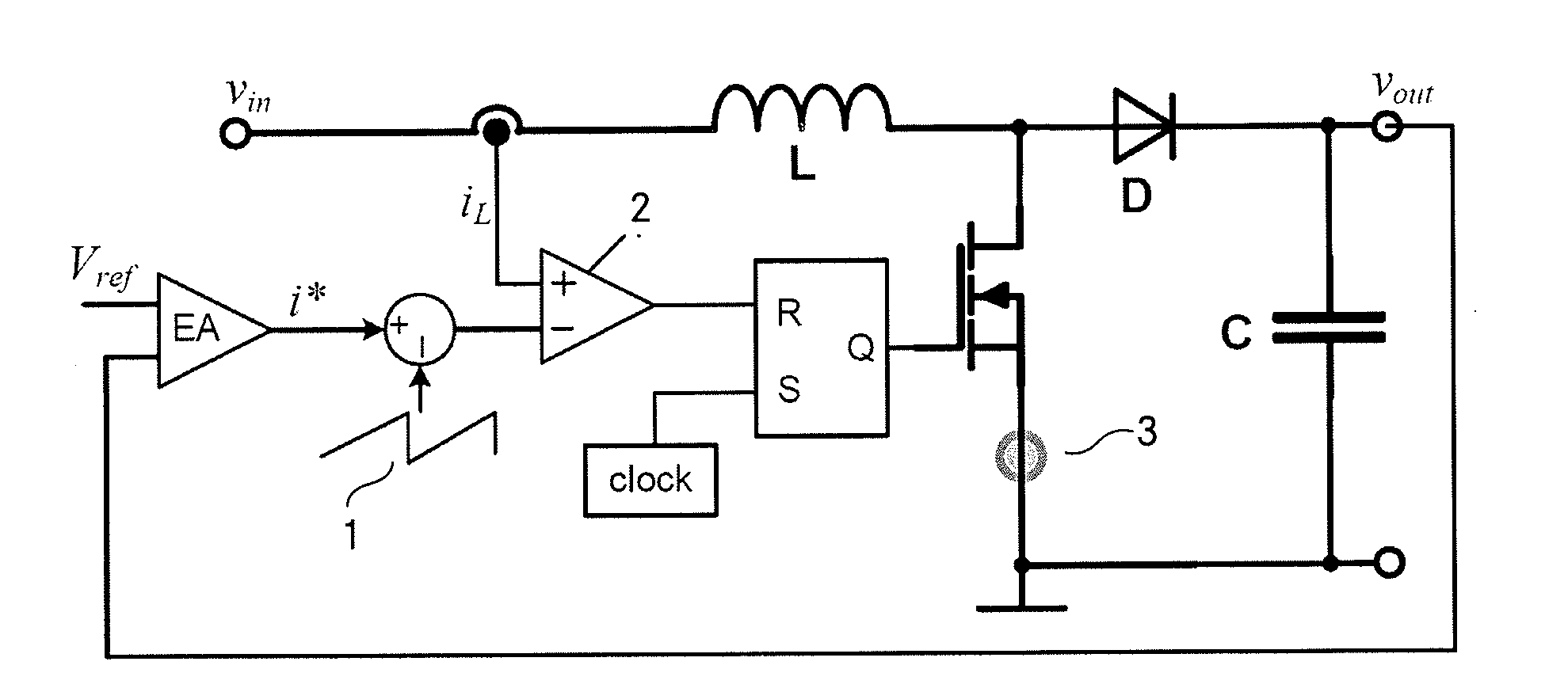
[0034]Current mode control is well known in prior art. The control blocks of a boost converter with outer voltage loop and inner peak current control loop with analog slope compensation is shown in FIG. 1. The basic principles of peak current mode control and the need of slope compensation are as follows.

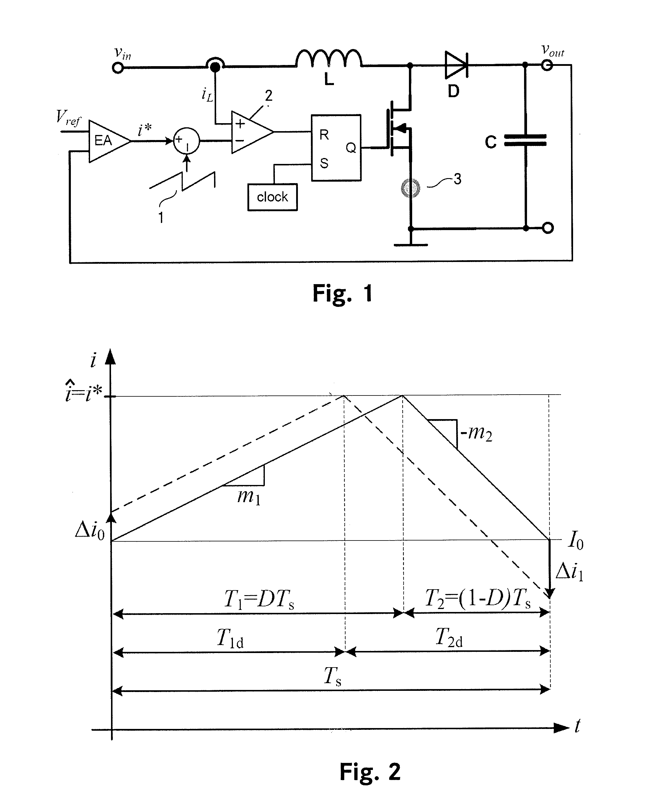
[0035]In order to derive the stability criterion of peak current mode controlled CCM converters which characterizes the transition to subharmonic oscillations, the operation without slope compensation shall be analyzed in a first step. Therefore we refer to FIG. 2 where an undisturbed (solid stroke) and a disturbed (dashed stroke) inductor current are plotted versus a single switching period Ts. Both inductor current shapes have the same rising slope m1, falling slope m2 and peak value î.

[0036]For the undisturbed case (solid line in FIG. 2) it can be directly derived

î=m1·T1+I0  (1)

as well as

î−m2·T2=I0  (2)

whereas for a disturbance of Δi0 (dashed line in FIG. 2)

î=Δi0+m1·T1d+I0  (3)

an...


PUM


Abstract

A digital slope compensation apparatus and method for a switched-mode power supply use a sensor for sensing and generating an analog inductor current (iL) of the switched-mode power supply, a comparator (2) for generating a trigger signal according to a comparison of an analog current threshold level and the analog inductor current (iL), and a pulse width modulator (PWM) for controlling the operation of a switched-mode power supply, wherein the pulse width modulator (PWM) is arranged to be triggered by the trigger signal of the comparator. A first analog to digital converter is arranged for converting an analog output voltage (Vout) of the switched-mode power supply into a digital output voltage, means are arranged for transforming the digital output voltage into a digital current threshold level (icmp) and a digital to analog converter is arranged for generating the analog current threshold level according to the digital current threshold level (icmp).

Description

TECHNICAL FIELD[0001]The invention relates to a digital slope compensation apparatus for a switched-mode power supply, wherein a sensor is used for sensing an analog inductor current of the switched-mode power supply, a comparator is used for generating a trigger signal according to a comparison of an analog current threshold level and the analog inductor current, and a pulse width modulator is used for controlling the operation of a switched-mode power supply, wherein the pulse width modulator is arranged to be triggered by the trigger signal of the comparator. The invention further relates to a digital slope compensation method for a switched-mode power supply, wherein an analog inductor current of the switched-mode power supply is sensed, a trigger signal according to a comparison of an analog current threshold level and the analog inductor current is generated, and a pulse width modulated signal is triggered by the trigger signal to control operation of the switched-mode power s...

Claims


Application Information

Patent Timeline
IPC IPC(8): G05F1/10
CPCH02M3/156
Inventor SCHAFMEISTER, FRANKGROTE, TOBIAS
Owner DELTA ELECTRONICS (THAILAND) PUBLIC CO LTD
Why Eureka
Try Eureka