

Power control
- Summary
- Abstract
- Description
- Claims
- Application Information
AI Technical Summary
Benefits of technology
Problems solved by technology
Method used
Image

Examples
Embodiment Construction
[0058]In broad terms, the invention provides for stepped / incremental changes in current provided by a high-power IPT pick-up so as to avoid large substantially instantaneous changes. The invention additionally or alternatively provides for wave-shaping of the current, so as to, for example, obtain a unity power factor.
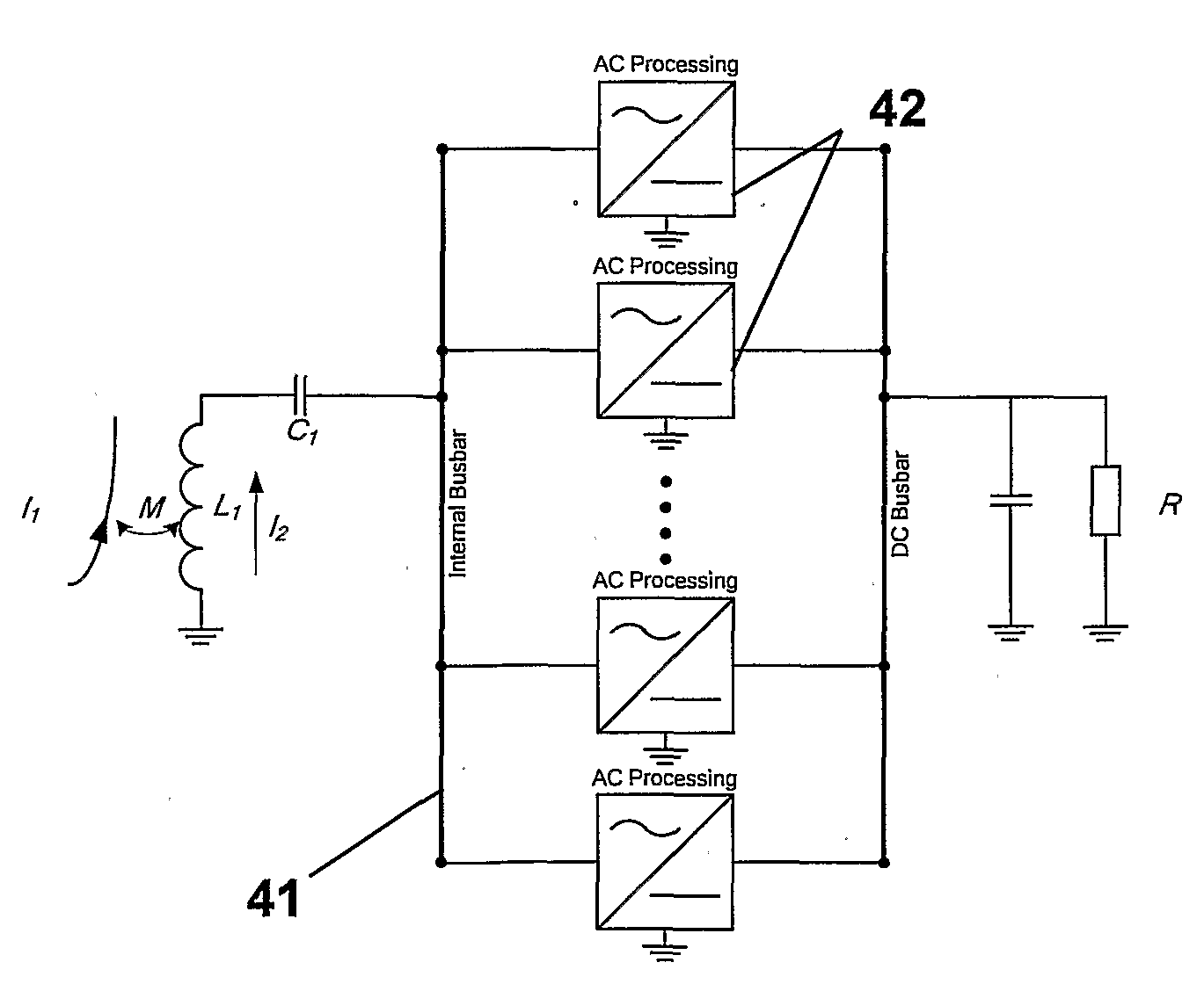
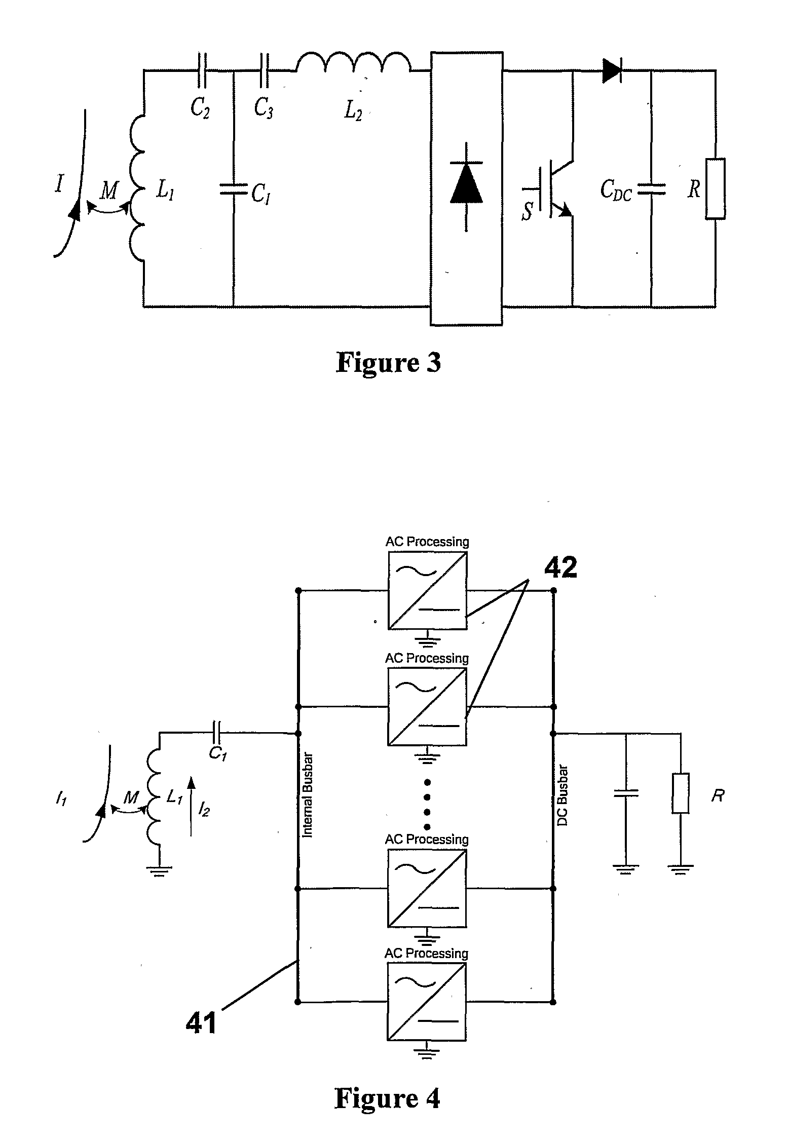
[0059]A high-power pick-up controller according to a preferred embodiment of the invention is shown in FIG. 4. The apparatus of FIG. 4 includes a pick-up inductor L1 that is fully series tuned with capacitor C1 to provide Internal Busbar 41 with an output voltage at the resonant frequency essentially the same as the open circuit voltage of the pick-up coil VOC. Internal Busbar 41 acts like a voltage source and would be dangerous if it were to be short-circuited. However, it is only ever used internally in the pick-up controller and so short-circuits are unlikely and easily protected against, in any event, with a simple fuse, if required.
[0060]A number of processing mea...
PUM
 Abstract
Description
Claims
Application Information