Combination MRI and Radiotherapy Systems and Methods of Use

a radiotherapy and combination technology, applied in the field of combination radiotherapy and mri systems, can solve the problems of difficult to achieve adequate accuracy, difficulty in achieving adequate accuracy, and difficulty in achieving the requirement for patient positioning accuracy

Inactive Publication Date: 2011-05-19
NAVOTEK MEDICAL
View PDF8 Cites 181 Cited by
  • Summary
  • Abstract
  • Description
  • Claims
  • Application Information

AI Technical Summary

Benefits of technology

[0044]Optionally, the magnetic field source is sufficiently well shielded magnetically such that the magnetic field used for imaging is less than 100 gauss throughout any volume where the radiation source is located during imaging.
[0045]Optionally, the controller and magnetic field source are configured such that when the controller ramps the magnetic field source down, the magnetic field is less than 100 gauss in any volume in which the system is configured to receive part of the body of the patient during radiotherapy.

Problems solved by technology

Such imaging systems are not mechanically connected to the radiation therapy system.
Accuracy of patient positioning is important, and it is quite difficult to attain adequate accuracy, since many internal organs seen during the CT planning scan (e.g. the prostate) are not visible or palpable from outside the body.
This requirement for accuracy in patient positioning poses a difficulty, in that commercial linac systems generally do not include built-in CT or MRI scanners.
Methods using external markers are simple but their accuracy is low, using, as they do, the assumption that the external marker remains at the same position and orientation relative to the tumor throughout the entire radiotherapy regimen.
The assumption is poor for soft-tissue tumors whose positions can change from day to day, from hour to hour, and even from minute to minute.
The assumption is poor for certain internal organs such as the prostate gland (and any associated tumor) since the spatial relationship between the organ and the external marker will vary depending on the volume of the bladder.
The use of external fiducial markers is even less accurate in areas of the body where breathing motion affects the tissue in question, e.g., in lung or liver tumors.
Megavoltage imaging (using the treatment beam to produce a crude CT-like image) produces low quality images in which it is often not possible to distinguish soft tissues.
Another source of positioning inaccuracy is due to the changes in tumor geometry over the course of the treatment.
However, the costs of repeatedly imaging the tumor are often quite high, as are the costs, in time and manpower, of recalculating the radiation dose.
In any case, imaging techniques that do not show the soft tissue cannot provide such information.
However, when MRI images are obtained at a separate location, with the images transferred to a radiation-planning computer, the potential for inaccuracy remains.
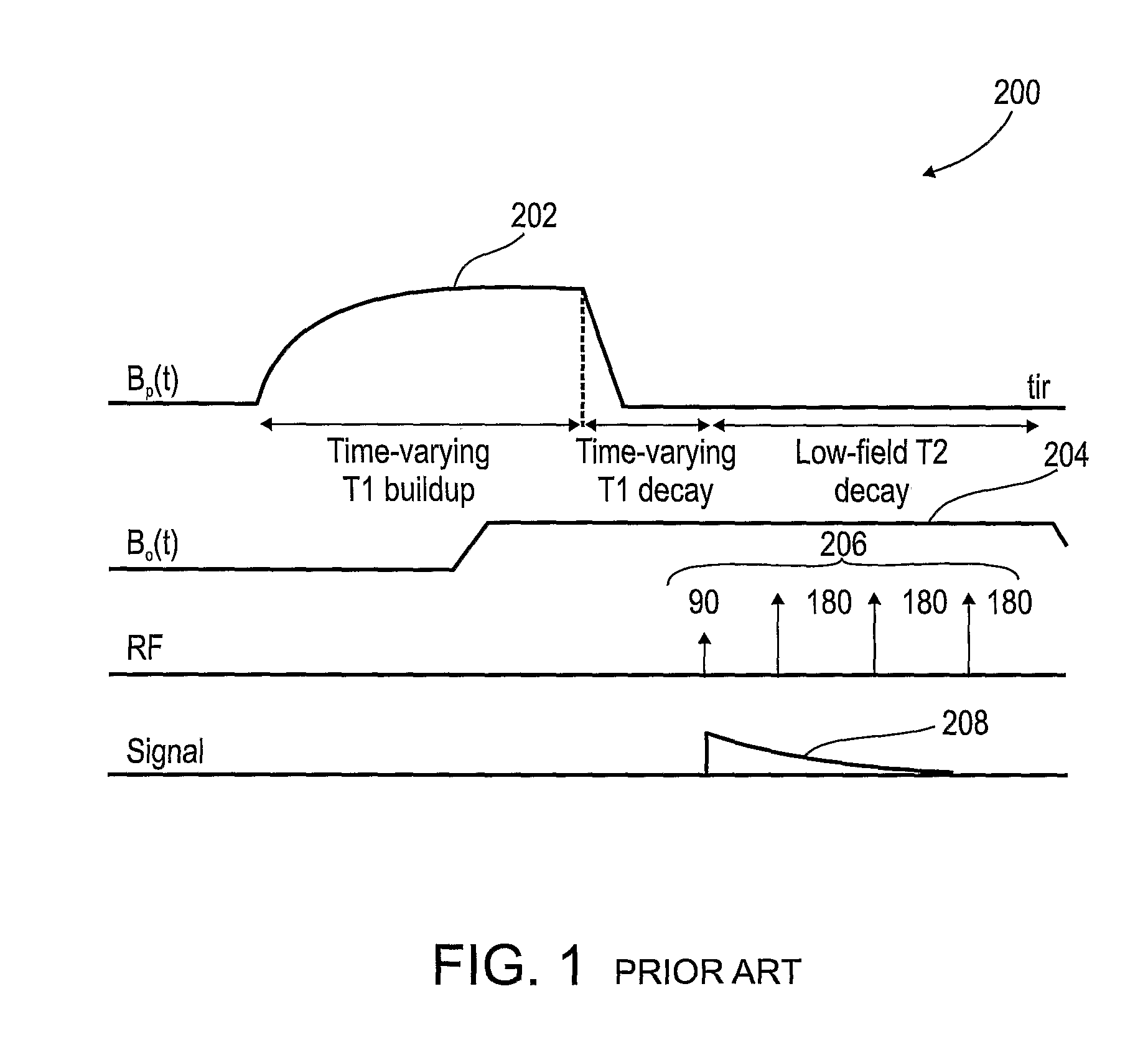
Standard MRI systems, in which a high field is present both during the signal excitation and during the signal readout, suffer from increased artifacts from inhomogeneity, susceptibility, and chemical shifts, as compared with low field systems.
In most implementations of PMRI, the polarizing magnet is resistive, due to the technical difficulty of pulsing a superconducting magnet as well as the increased cost of superconducting magnets relative to resistive magnets.
These papers point out problems introduced by the linac and the MRI system interfering with each other.
1) The components of the MRI system form a physical barrier to the linac's radiation beam, attenuating and scattering the beam.
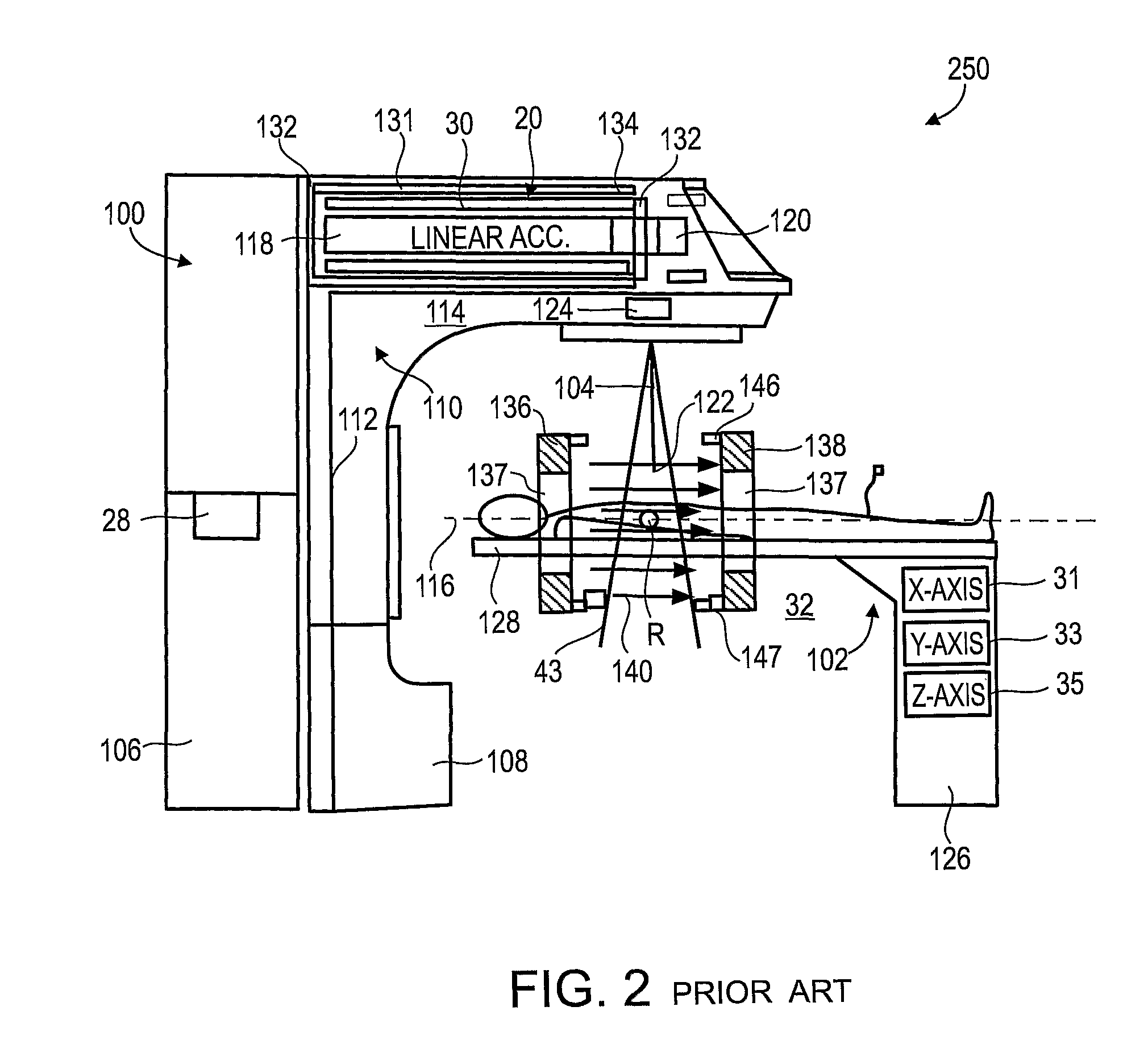
2) The magnetic field created by the MRI system usually extends beyond the physical volume of the MRI system, and any such external magnetic fields imposed upon the linac may adversely affect the electron beam used to create the linac's radiation, by changing the path of the electron beam so it is not accelerated properly, or misses its target.
3) A magnetic field imposed upon the patient skews the radiation dose distribution within the patient, due to its effect on secondary electrons produced inside the patient by the incident x-rays or gamma rays, especially in low density organs such as the lungs. The problem of calculating the dose distribution is made more difficult by the fact that the magnetic field is inhomogeneous inside the body, due to the magnetic susceptibility of the body. It is very difficult to model or measure this inhomogeneity accurately in-vivo and therefore it is very difficult to take it into account during radiation planning.
4) The RF section of the linac, used for accelerating the electron beam, introduces substantial noise into the MRI image, especially if the Larmor frequency of the MRI magnetic field is near an RF frequency used by the linac, or a harmonic of it.
5) Ferromagnetic components of the linac distort the magnetic field in the neighborhood, leading to artifacts and loss of resolution on the MRI image. Compensating for the field distortion is difficult because the linac typically is on a gantry that moves relative to the MRI system.
These devices only overcome the first problem listed above.
This method does not address the third problem mentioned above, i.e., the effect of the magnetic field on the target tissue dose.
However, low field MRI systems have the disadvantage that they require longer acquisition time than high field MRI systems, for the same signal-to-noise ratio and pixel size.
This could result in inefficient use of the expensive radiotherapy system if much more time is spent acquiring images than is spent irradiating the patient, and the longer treatment sessions may be more uncomfortable for the patient.
Whole-body resistive MM magnets having a field strength above about 0.35 T are difficult to fabricate.
The heat generated in the magnet coils is not easily dispersed.
The currents in resistive magnet coils are not readily stabilized at the level required for MRI.
This latter difficulty increases with increasing magnet current (i.e., increasing magnetic field strength).

Method used


Image

  • Combination MRI and Radiotherapy Systems and Methods of Use
  • Combination MRI and Radiotherapy Systems and Methods of Use
  • Combination MRI and Radiotherapy Systems and Methods of Use

Examples


Embodiment Construction

[0063]The present invention, in some embodiments thereof, relates to combination radiotherapy and MRI systems and methods of using them, and more particularly, but not exclusively, to combination systems in which the main MRI magnet can be quickly ramped up for imaging and down for radiotherapy. Alternating periods when the field has been ramped up, and MRI images are acquired, with periods when the field has been ramped down, and doses of radiation are applied to a tumor or other target in a patient, may allow nearly real-time MRI images of the target, and hence more accurate application of radiation, while avoiding the problems, listed above, that make it difficult to acquire MRI images during the application of radiation to a patient.

[0064]An exemplary embodiment of the invention concerns a combined MRI and radiotherapy system, in which an MRI magnetic field source is ramped up to a magnetic field used for imaging, and ramped down to a much weaker field, or to zero magnetic field...


PUM


Abstract

A combination MRI and radiotherapy system comprising: a) an MRI system for imaging a patient receiving radiotherapy, comprising a magnetic field source suitable for generating a magnetic field of strength and uniformity useable for imaging, capable of being ramped up to said magnetic field in less than 10 minutes, and ramped down from said magnetic field in less than 10 minutes; b) a radiation source configured for applying radiotherapy; and c) a controller which ramps the magnetic field source down to less than 20% of said magnetic field strength when the radiation source is to be used for radiotherapy, and ramps the magnetic field source up to said magnetic field strength when the MRI system is to be used for imaging.

Description

RELATED APPLICATION / S[0001]The present application claims benefit under 35 USC 119(e) from U.S. provisional patent application 61 / 069,277, filed on Mar. 12, 2008.[0002]The contents of the above document are incorporated by reference as if fully set forth herein.FIELD AND BACKGROUND OF THE INVENTION[0003]The present invention, in some embodiments thereof, relates to combination radiotherapy and MRI systems and methods of using them, and more particularly, but not exclusively, to combination systems in which the main MRI magnet can be quickly ramped up for imaging and down for radiotherapy.[0004]In radiation therapy (also known as radiotherapy), ionizing radiation is used to destroy tissues affected by proliferative tissue disorders such as cancer. In external beam radiotherapy, a radiation source is placed outside the body of the patient and the target within the patient is irradiated with an external radiation beam. Two types of external radiation sources are typically used—radiatio...

Claims


Application Information

Patent Timeline
Patent Type & Authority Applications(United States)
IPC IPC(8): A61B5/055A61N5/00
CPCA61N5/1049G01R33/4812G01R33/445A61N2005/1055
Inventor KOMBLAU, GIORANEUSTADTER, DAVID MAIERSTOKAR, SAUL
Owner NAVOTEK MEDICAL
Why Eureka
Try Eureka