Damage sensors and processing arrangements therefor

a technology of damage sensors and processing arrangements, applied in the direction of electrical/magnetic measuring arrangements, instruments, structural/machine measurement, etc., can solve the problem that the conductive track gauge does not provide an indication of the size of the crack, and achieve the effect of convenient provision and monitoring

Inactive Publication Date: 2011-05-19
BAE SYSTEMS PLC
View PDF9 Cites 16 Cited by
  • Summary
  • Abstract
  • Description
  • Claims
  • Application Information

AI Technical Summary

Benefits of technology

[0011]The present inventors have realised it would be desirable to provide a crack gauge (or other damage sensor) that can be easily provided and monitored.

Problems solved by technology

For example, although conductive-track gauges as disclosed in WO 2007 / 088395 A1 can be used to sense the location (i.e. where along the track) a crack occurs, nevertheless the conductive-track track gauges do not provide an indication of the size of a crack.

Method used


Image

  • Damage sensors and processing arrangements therefor
  • Damage sensors and processing arrangements therefor
  • Damage sensors and processing arrangements therefor

Examples


Embodiment Construction

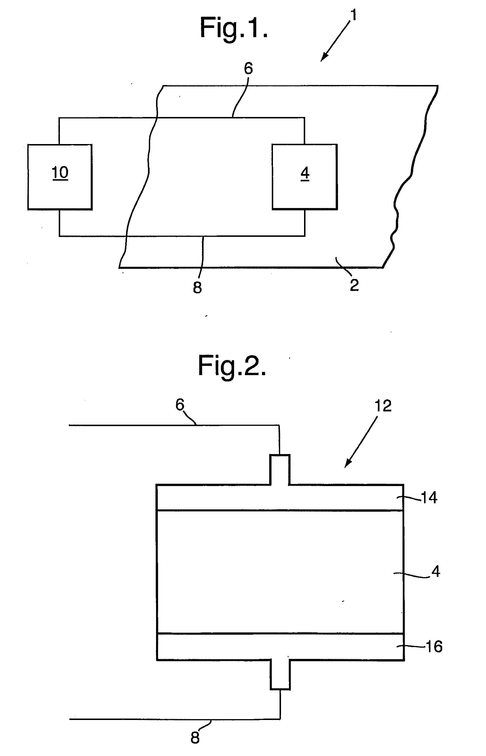
[0065]FIG. 1 is a schematic illustration of an example of a crack gauge system 1 for sensing cracks on the surface of a substrate 2. The crack gauge system 1, which does not form part of the prior art, is described as an example that is useful for understanding the examples of crack gauges described below with reference to FIGS. 2-6, and is further useful as a comparative example to aid further understanding of embodiments of crack gauge systems described later below with reference to FIGS. 7-9.

[0066]The crack gauge system 1 comprises an example of a resistive crack gauge, here a direct write resistive element 4 applied to the surface of the substrate 2. The direct write resistive element 4 is connected via two conducting connections, namely first conducting connection 6 and second conductive connection 8, across a processor 10.

[0067]The direct write resistive element 4 is formed of an area of resistive ink (or paste) applied to the surface of the substrate 2. In this example the di...


PUM


Abstract

A damage sensing system, and a method of sensing damage using the system, are described. The system comprises: a plurality of tuned circuits arranged in parallel, each tuned circuit having a different resonant frequency; and processing means for discriminating the response of the different tuned circuits according to their respective different resonant frequencies, for example by processing changes in the respective Q-factors of the respective tuned circuits; wherein each of the plurality of tuned circuits comprises a respective damage sensor, each damage sensor comprising at least one direct write resistive element applied to an area of a substrate by a direct write process. Each tuned circuit may comprise a common resistor in series with the respective damage sensor. The plurality of the tuned circuits may be coupled to the processing means by a shared single pair of external connections.

Description

FIELD OF THE INVENTION[0001]The present invention relates to damage sensors and processing arrangements therefor. The present invention is particularly suited to, but not limited to, crack gauges. More particularly, but not exclusively, the present invention relates to damage sensors for detecting the presence and occurrence of damage to a broad variety of structures such as aircraft, ships and bridges.BACKGROUND[0002]Structures such as aircraft airframes, ships' hulls, and bridges require regular inspections to check for damage. Inspections are currently usually performed manually according to a schedule. These scheduled inspections are precautionary, and, often, no damage is found. Such inspections are very time consuming and thus costly, since the structure will be out of use whilst the inspection is carried out. However, they are necessary since the consequences of structural failure can be catastrophic.[0003]A number of damage or defect sensor systems are currently being develo...

Claims


Application Information

Patent Timeline
Patent Type & Authority Applications(United States)
IPC IPC(8): G06F19/00
CPCG01B7/16G01N2203/0617G01N2203/0244G01M5/00
Inventor SIDHU, JAGJITFOOTE, PETER DAVID
Owner BAE SYSTEMS PLC
Why Eureka
Try Eureka