Control of humidifier chamber temperature for accurate humidity control

a technology of humidity control and humidifier chamber, which is applied in the direction of inhalators, medical devices, other medical devices, etc., can solve the problems of ineffective therapy regime, circuit failure, and difficulty in ensuring the quality of gas delivery to the user with substantially the correct characteristics

Active Publication Date: 2011-05-26
FISHER & PAYKEL HEALTHCARE LTD
View PDF13 Cites 85 Cited by
  • Summary
  • Abstract
  • Description
  • Claims
  • Application Information

AI Technical Summary

Problems solved by technology

One of the problems that has been encountered with systems that provide a flow of heated, humidified gases to a patient via a gases conduit and an interface is that of adequately controlling the characteristics of the gas.
A therapy regime can become ineffective if the gases are not delivered to the patient with the correct or required characteristics.
Breathing circuits are not steady-state systems, and it is difficult to ensure the gases are delivered to a user with substantially the correct characteristics.
It can be difficult to achieve this result over a range of ambient temperatures, ambient humidity levels, and a range of gas flows at the point of delivery.
A number of external variables can affect the gases within a breathing circuit and make it difficult to deliver the gases to the user at substantially the right temperature, flow rate and humidity.
This cooling can lead to ‘rain-out’ within the conduit (that is, condensate forming on the inner surface of the conduit).
Rain-out is extremely undesirable for reasons that are explained in detail in WO 01 / 13981.
One possible disadvantage of systems and methods which estimate the gases characteristics (such as the system and method disclosed in WO 2001 / 13981) is that the estimations and algorithms used are not as accurate as is necessary.
There are many variable factors that can detrimentally effect the accuracy of the calculation algorithms used by the controller.
For example, the apparatus and in particular the humidifier chamber can be subject to convective heat loss (‘draft’) which is created by external airflows, particularly in ventilated spaces.
The system disclosed in WO 2001 / 13981 is unlikely to be able to provide the control precision necessary to control humidity accurately without substantial rainout occurring.
If the air coming into the chamber is warm and the air temperature is increasing with an increase in flow, then the inaccuracy of a set calculation algorithm will increase.
Displaying the temperature reading is often inadequate for a user to make an informed decision, as the temperature does not always directly relate to the gases humidity state.
A specific therapy regime may call for a high or 100% humidity level, but this can be undesirable for users who use a mask, as the conditioned gas with high humidity can feel uncomfortable for a user on their skin.
As the gases characteristics are interdependent, a change in the flow rate may lead to a significant change in the humidity, temperature or oxygen fraction of the gases delivered to a user.

Method used


Image

  • Control of humidifier chamber temperature for accurate humidity control
  • Control of humidifier chamber temperature for accurate humidity control
  • Control of humidifier chamber temperature for accurate humidity control

Examples


Embodiment Construction

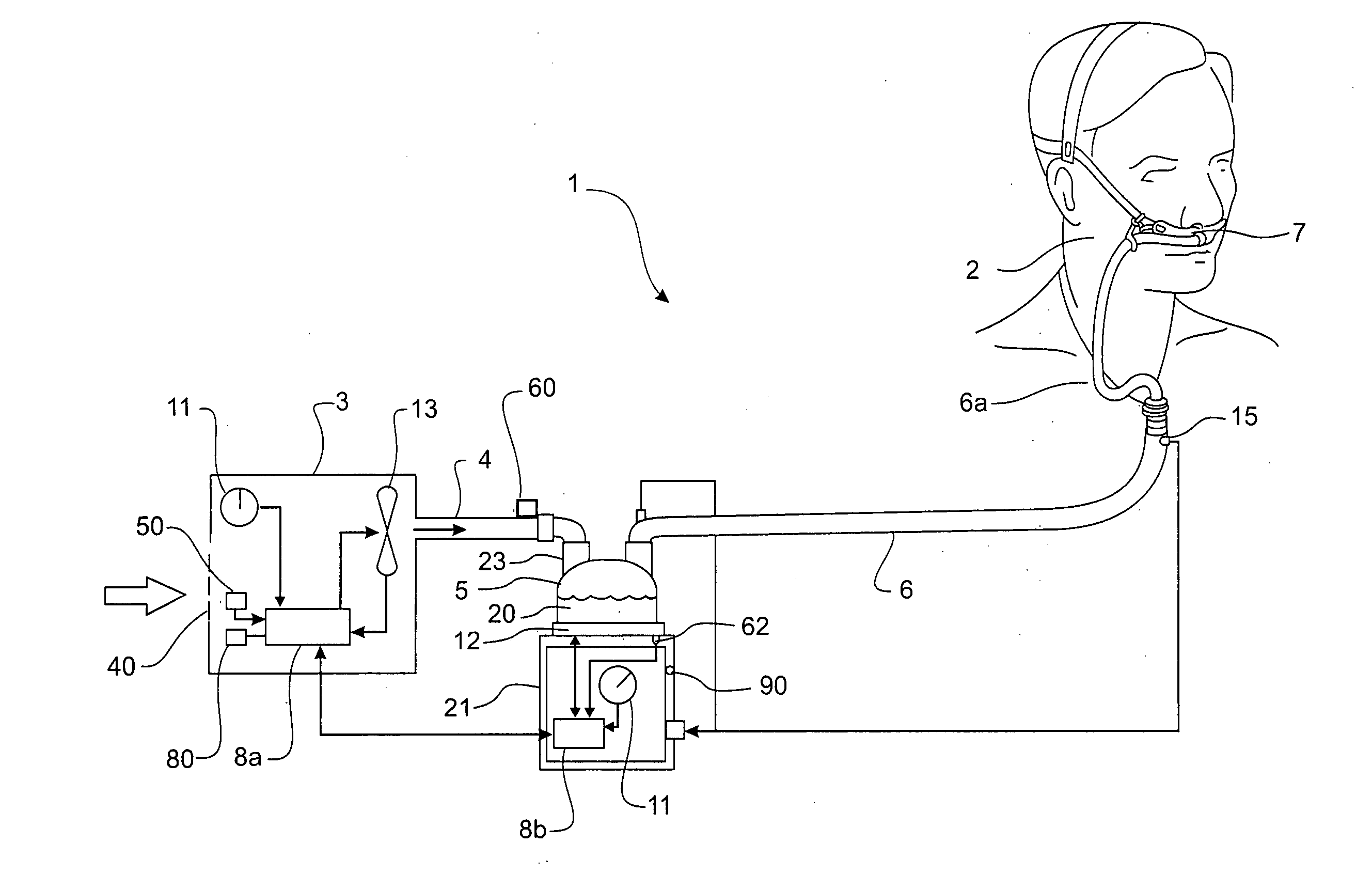
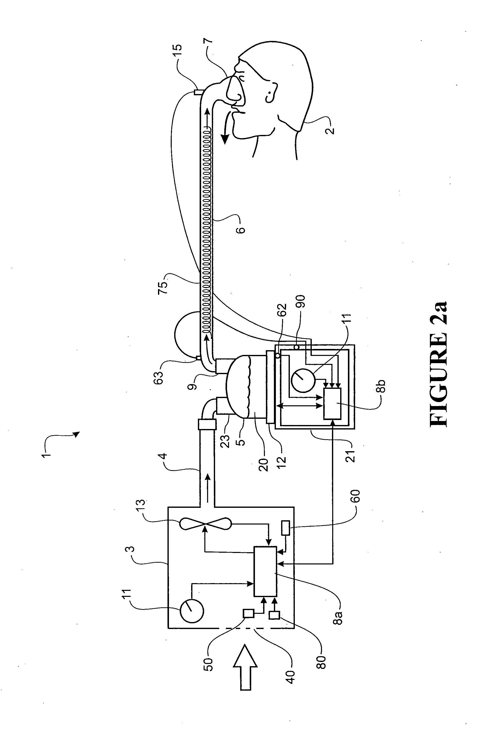
[0055]A schematic view of a user 2 receiving air from a modular assisted breathing unit and humidifier system 1 according to a first variant or embodiment of the invention is shown in FIGS. 2a and 2b. The system 1 provides a pressurised stream of heated, humidified gases to the user 2 for therapeutic purposes (e.g. to reduce the incidence of obstructive sleep apnea, to provide CPAP therapy, to provide humidification for therapeutic purposes, or similar). The system 1 is described in detail below.

[0056]The assisted breathing unit or blower unit 3 has an internal compressor unit, flow generator or fan unit 13—generally this could be referred to as a flow control mechanism. Air from atmosphere enters the housing of the blower unit 3 via an atmospheric inlet 40, and is drawn through the fan unit 13. The output of the fan unit 13 is adjustable—the fan speed is variable. The pressurised gases stream exits the fan unit 13 and the blower unit 3 and travels via a connection conduit 4 to a hu...


PUM


Abstract

A breathing assistance system for delivering a stream of heated, humidified gases to a user, comprising a humidifier unit which holds and heats a volume of water, and which in use receives a flow of gases from a gases source via an inlet port, the flow of gases passing through the humidifier and exiting via an exit port, the system further having a temperature sensor which measures the temperature of the gases exiting the humidifier unit, an ambient temperature sensor which measures the temperature of gases before they enter the humidifier unit, and a flow sensor which measures the flow rate of the gases stream, the system also having a controller which receives data from the temperature and flow sensors, and which determines a control output in response, the control output adjusting the power to the humidifier unit to achieve a desired output at the humidifier unit exit port.

Description

FIELD OF THE INVENTION[0001]This invention relates to methods and apparatus for controlling the humidity level and flow rate of gases in a device that provides a stream of heated, humidified gases to a user for therapeutic purposes. This invention particularly relates to methods and apparatus for controlling the humidity of a gases stream in devices that provide humidified air for: respiratory humidification therapy, high-flow oxygen therapy, CPAP therapy, Bi-PAP therapy, OPAP therapy, etc, or humidification of gases used for insufflation or keyhole surgery.BACKGROUND[0002]Devices or systems for providing a humidified gases flow to a patient for therapeutic purposes are well known in the art. Systems for providing therapy of this type (for example respiratory humidification) have a structure where gases are delivered to a humidifier chamber from a gases source. As the gases pass over the hot water, or through the heated, humidified air in the humidifier chamber, they become saturate...

Claims


Application Information

Patent Timeline
Patent Type & Authority Applications(United States)
IPC IPC(8): A61M16/16
CPCA61M16/1075A61M16/16A61M2205/3368A61M16/0465A61M16/0051A61M16/1095A61M16/0069A61M16/0012A61M16/0666A61M16/0875A61M16/109A61M16/161A61M16/0841A61M16/026A61M16/1085
Inventor TATKOV, STANISLAVCRONE, CHRISTOPHER MALCOLMHAWKINS, PETERHAN, JAE CHULO'DONNELL, KEVIN PETERSOMERVELL, ANDREW ROBERT DONALD
Owner FISHER & PAYKEL HEALTHCARE LTD
Why Eureka
Try Eureka