Electronic circuit and IC tag

Active Publication Date: 2011-05-26
LINTEC CORP
View PDF5 Cites 4 Cited by
  • Summary
  • Abstract
  • Description
  • Claims
  • Application Information

AI Technical Summary

Benefits of technology

[0016]The electronic circuit and an IC tag incorporating the electronic circuit of the present invention are excellent in folding endurance property, and can be or have an electronic circuit which is hard to break even if the electronic circuit is folded.

Problems solved by technology

However, if there is a large difference between the line width of the connected circuit line and the size of the plane flat surface of the terminal portion (for example, see Patent reference 1), there is a case that the circuit line breaks because the stress concentration is caused at a position near the junction where the terminal portion is connected to the circuit line, when the electronic circuit is folded.
If the circuit line of the electronic circuit is broken, the function of the IC tag is lost, and the management can not be performed by confirming the recorded information.

Method used


Image

  • Electronic circuit and IC  tag
  • Electronic circuit and IC  tag
  • Electronic circuit and IC  tag

Examples


example 1

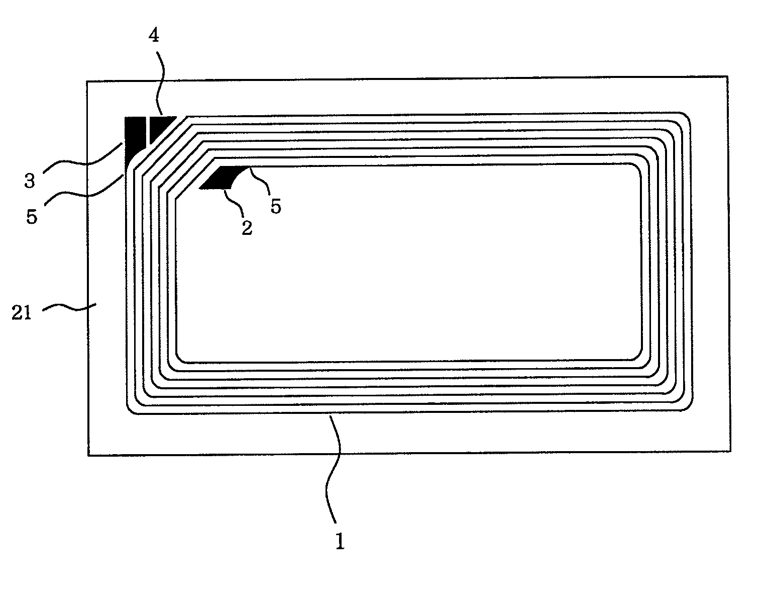
[0094]On the copper foil surface of a copper foil laminated sheet (trade name “Nikaflex F-10T50C-1”, produced by NIKKAN INDUSTRIES Co., Ltd.) in which the copper foil (having thickness of 35 μm) and a polyethylene terephthalate film (having thickness of 50 μm) are laminated, a resist pattern was printed in the figure of the circuit line 1, the terminal portion 2, the terminal portion 3 and the terminal portion 4 by screen printing method. And then, the copper foil of the useless portion was removed by etching to form the integral wiring pattern as shown in FIG. 1. The line width of the circuit line 1 was 200 μm. The length in the long side direction of the tetragon ring circuit line was 61 mm, and the length of the short side direction of the tetragon ring circuit line was 32 mm.

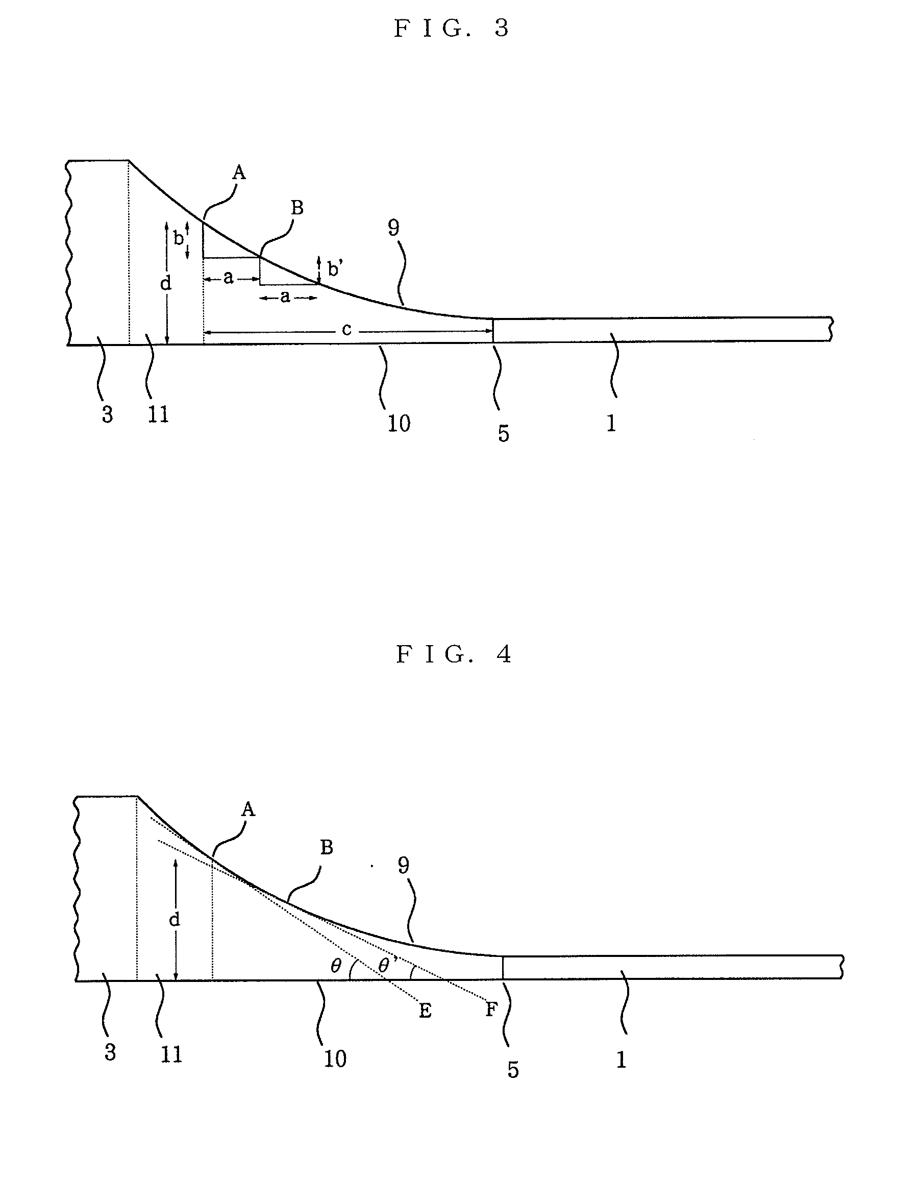
[0095]The terminal portion 2 was connected to the end of the most inside circuit line 1 at the junction 5, and has a plane width gradually-increasing portion from just back position of the junction. The leng...

example 2

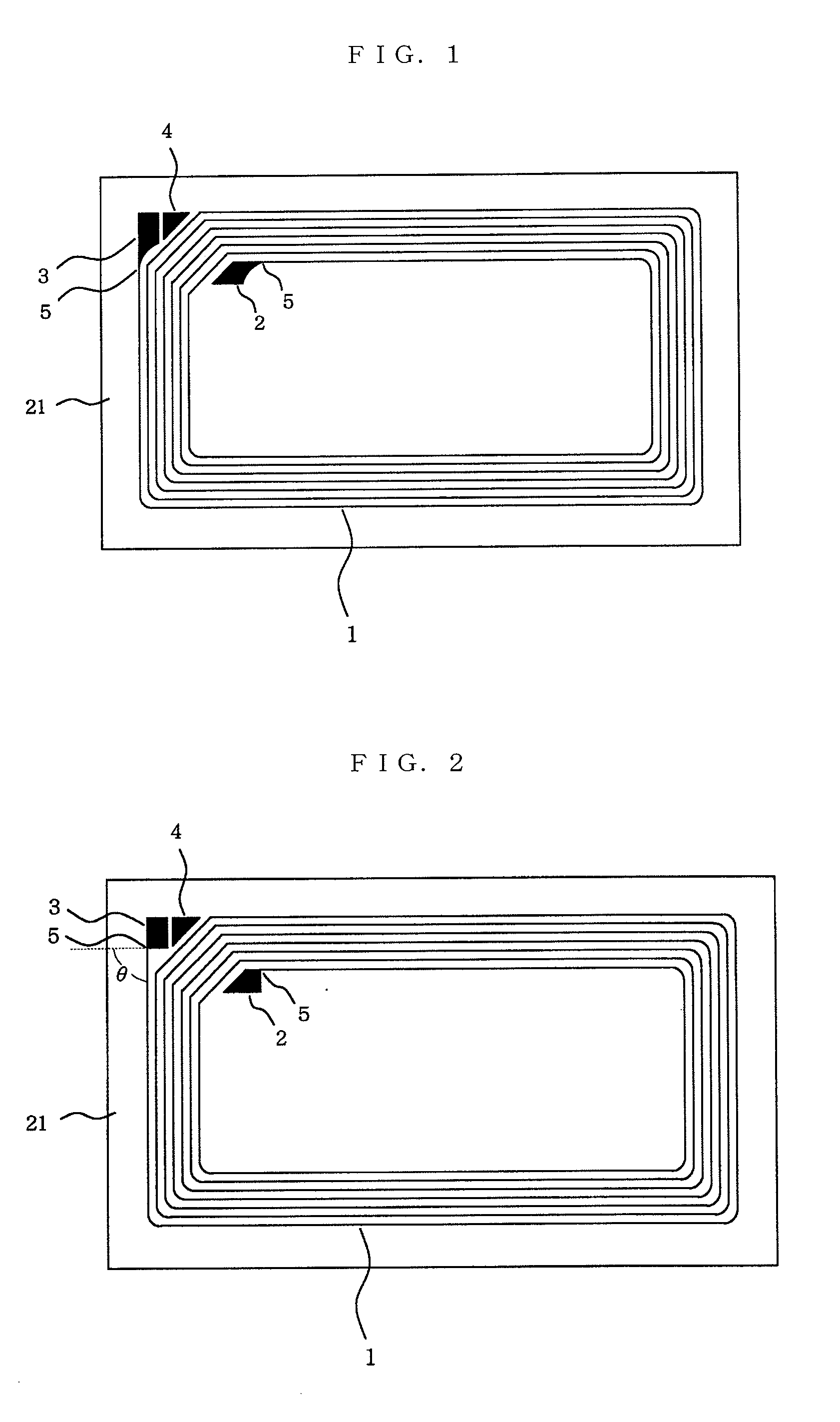
[0103]The IC tag was prepared in the same method as described in Example 1 except that with respect to the terminal portion 2, the length in the long side direction of the plane width gradually-increasing portion was 3.5 mm, and the maximum plane width of the plane width gradually-increasing portion was 3.5 mm, and one side edge of the plane width gradually-increasing portion was a concave curved line figure (curvature: a figure of the circular arc having 3.5 mm in radius R), and with respect to the terminal portion 3, the length in the short side direction of the plane width gradually-increasing portion was 3.3 mm, and the maximum plane width of the plane width gradually-increasing portion was 2.7 mm, and one side edge of the plane width gradually-increasing portion was a concave curved line figure (curvature: a figure of the circular arc having 3.5 mm in radius R). Thus, 40 pieces of the IC tag were produced.

[0104]The operation of the IC tag was confirmed by conducting a reading a...


PUM


Abstract

The present invention provides an electronic circuit which comprises a circuit line and a terminal portion connected to the circuit line, wherein the terminal portion has a folding endurance structure at a junction where the terminal portion is connected to the circuit line and the folding endurance structure of the terminal portion has a plane width gradually-increasing portion, in which the width of the terminal portion in plane view increases continuously or intermittently as the folding endurance structure of the terminal portion becomes away from the junction where the terminal portion is connected to the circuit line. The electronic circuit and an IC tag incorporating the electronic circuit of the present invention are excellent in folding endurance property, and can have an electronic circuit which is hard to break even if the electronic circuit is folded.

Description

FIELD OF THE INVENTION[0001]The present invention relates to a non-contact IC tag which can be used for personal certification, goods management, physical distribution and the like, and a structure of an electronic circuit which can be incorporated in the IC tag.BACKGROUND PRIOR ART[0002]Recently, a non-contact IC tag has been utilized to perform the personal certification, and article managements have been conducted to manage articles such as goods, storage articles and loadings by attaching a non-contact IC tag to articles such as goods, storage articles or loadings for management. For example, the article management has been conducted by attaching an IC tag which has recorded information such as production condition, stock state, cost information and usage condition to the articles and optionally further confirming the recorded information by an interrogator or the like.[0003]An electronic circuit incorporated in the non-contact IC tag or the like comprises a circuit line which f...

Claims


Application Information

Patent Timeline
IPC IPC(8): G06K19/077H05K1/00
CPCG06K19/07749G06K19/0775G06K19/07779H05K2201/09727H05K1/0271H05K3/4664H05K3/4685G06K19/07783
Inventor MATSUSHITA, TAIGAKATAKURA, KATSUMI
Owner LINTEC CORP
Why Eureka
Try Eureka