Low dropout regulator circuit without external capacitors rapidly responding to load change

a regulator circuit and low dropout technology, applied in the field of analog integrated circuit technology, can solve the problems of increasing system cost, increasing system design complexity, and large ripple of output voltage vout, and achieve the effect of low dropout regulator and greatly improving the load response speed of ldo

Inactive Publication Date: 2011-05-26
IPGOAL MICROELECTRONICS (SICHUAN) CO LTD
View PDF9 Cites 47 Cited by
  • Summary
  • Abstract
  • Description
  • Claims
  • Application Information

AI Technical Summary

Benefits of technology

An object of the present invention is to provide a low dropout regulator (LDO) circuit without external capacitors rapidly responding to load change, which is capable of controlling the output voltage by two loops of the slow operational amplifier loop and fast comparator loop, so that the load response speed of the LDO is greatly improved without the increase of the power consumption and external large capacitor.
The resistor Rc is a Miller compensation zero resistor. The capacitor Cc is a Miller compensation capacitor. The resistor Rc is connected with the capacitor Cc producing a left half plane zero to improve the phase margin of the LDO circuit. A value of the left half plane zero is 1 / (Rc*Cc). By pole splitting of the capacitor Cc, the main pole moves to low frequency, and the secondary pole moves to high frequency so that the operational amplifier is stabilized.
The circuit can control the output by two loops of a slow operational amplifier loop and a fast comparator loop so that the load response speed of the LDO is greatly improved without the increase of power consumption and external big capacitor.

Problems solved by technology

Therefore, it is necessary for the LDO circuit to be provided with a more than μF-level large capacitor by the exterior so as to provide a good load transient response thus increasing the system cost.
Furthermore, the resistance of the external capacitor's parasitic resistor will affect the loop stability of the LDO circuit, thus greatly increasing the complexity of the system design.
The output regulating transistor MP1 has a very large width-length ratio and a large gate parasitic capacitance, so the current of the operational amplifier must be very large for obtaining the GHz-level loop bandwidth, otherwise the deficiency of the loop bandwidth will cause the big ripple of the output voltage VOUT.
When the ripple of the output voltage VOUT exceeds ±10%, the LDO power supply system will not work properly.

Method used


Image

  • Low dropout regulator circuit without external capacitors rapidly responding to load change
  • Low dropout regulator circuit without external capacitors rapidly responding to load change
  • Low dropout regulator circuit without external capacitors rapidly responding to load change

Examples


Embodiment Construction

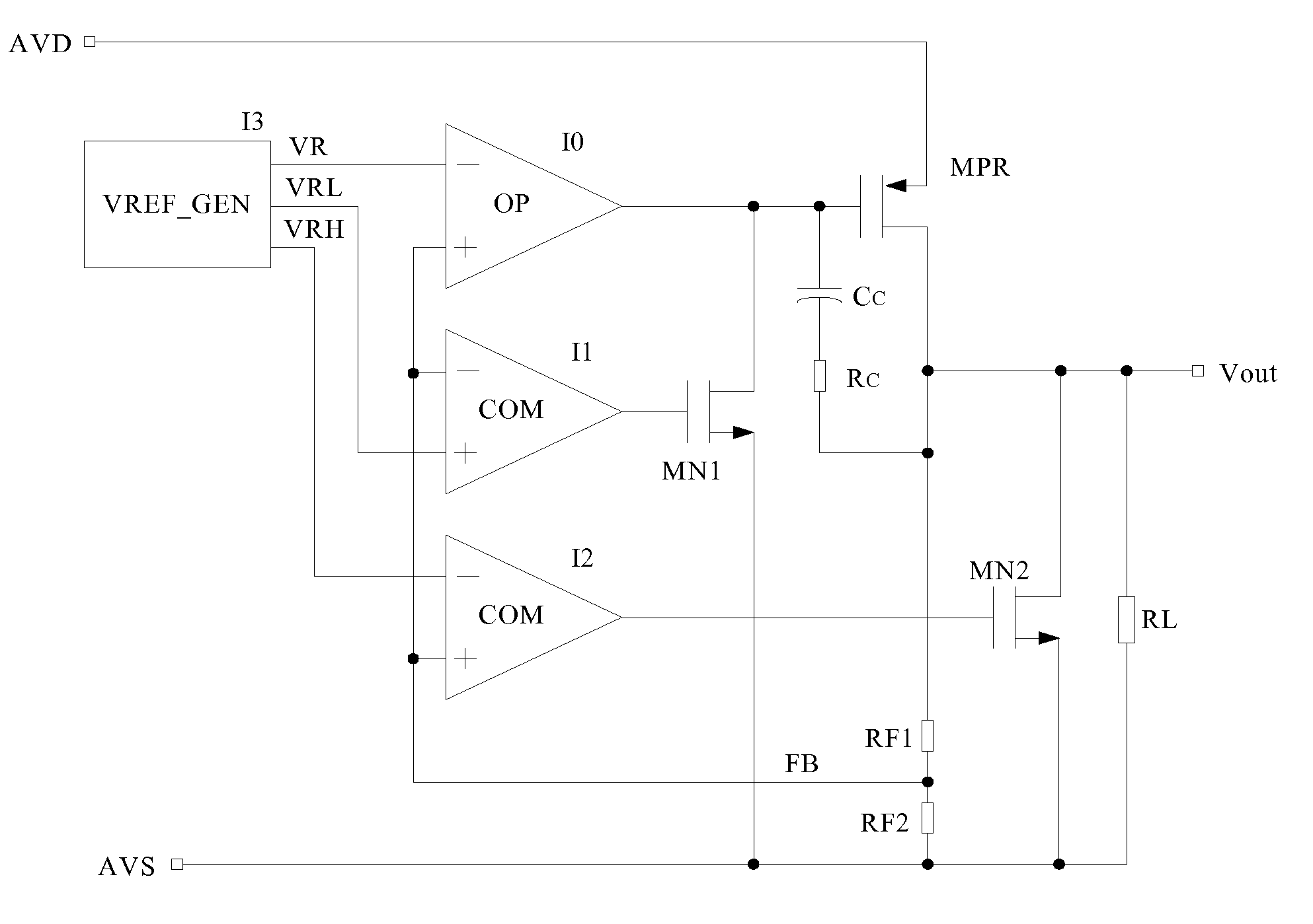
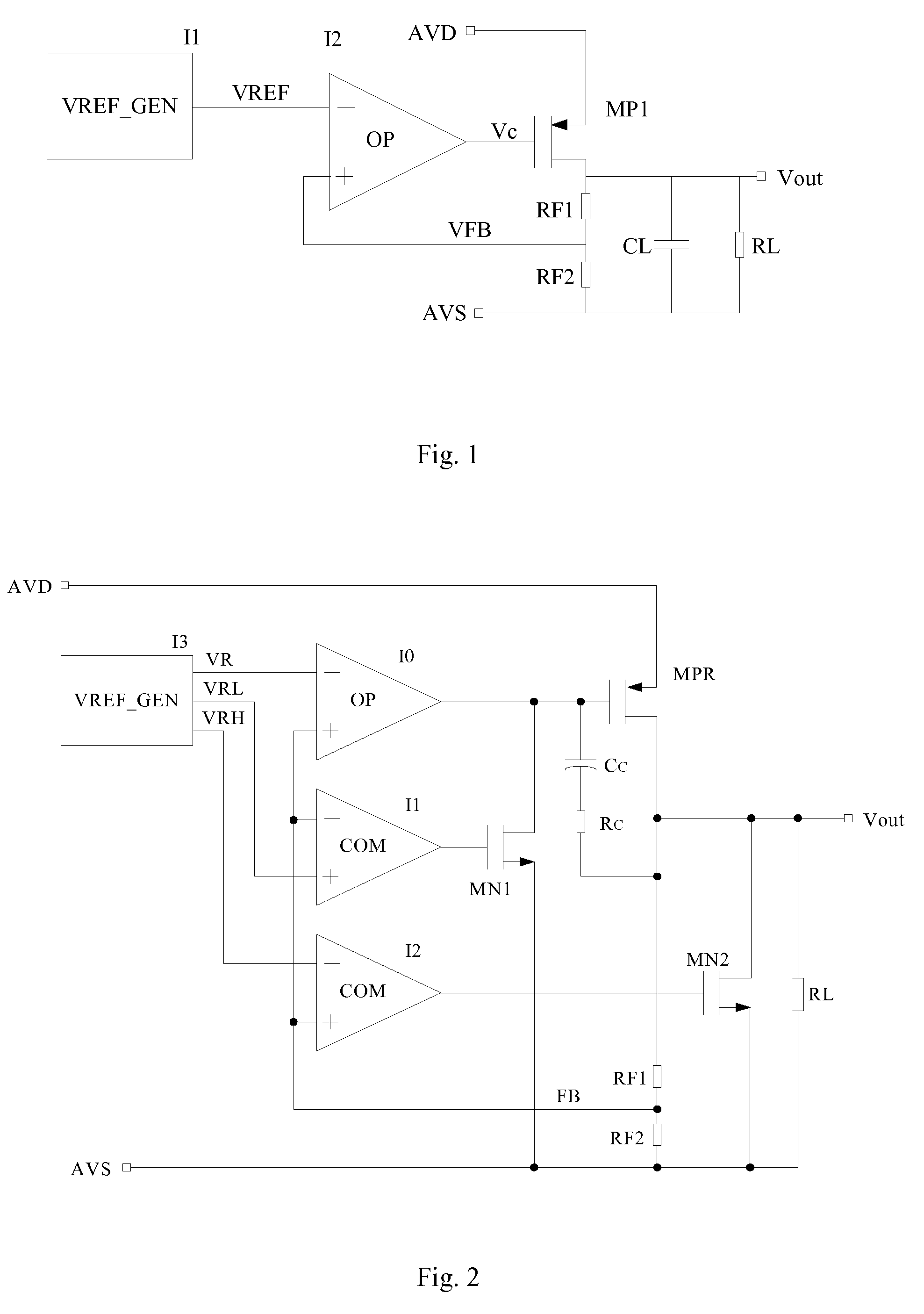
Referring to the FIG. 2, a low dropout regulator (LDO) circuit without external capacitors rapidly responding to load change according to a preferred embodiment of the present invention is illustrated, which comprises a slow pathway and a fast pathway for controlling voltage, wherein the slow pathway for providing precise output voltage comprises an operational amplifier I0, a driving transistor MPR, a resistor RF1 and a resistor RF2 forming an operational amplifier loop, and the fast pathway for responding to rapid load change comprises a comparator I1, a comparator I2, a field effect transistor (FET) MN1, a field effect transistor (FET) MN2, a driving transistor MPR, a resistor RF1 and a resistor RF2 forming a comparator loop.

The low dropout regulator (LDO) circuit without external capacitors rapidly responding to load change further comprises a reference voltage generating circuit 13 for providing the operational amplifier I0, the comparator I1 and the comparator I2 with three re...


PUM


Abstract

A low dropout regulator (LDO) circuit without external capacitors rapidly responding to load change includes a slow pathway and a fast pathway for controlling voltage, wherein the slow pathway for providing precise output voltage includes an operational amplifier I0, a driving transistor MPR, a resistor RF1 and a resistor RF2 forming an operational amplifier loop, and the fast pathway for responding to rapid load change includes a comparator I1, a comparator I2, a field effect transistor MN1, a field effect transistor MN2, a driving transistor MPR, a resistor RF1 and a resistor RF2 forming a comparator loop. The circuit is capable of controlling the output voltage by the slow operational amplifier loop and fast comparator loop, so that the load response speed of the LDO is greatly improved without the increase of the system power consumption and external big capacitors.

Description

BACKGROUND OF THE PRESENT INVENTION1. Field of InventionThe present invention relates to an analog integrated circuit technology, and more particularly to a low dropout regulator circuit without external capacitors rapidly responding to load change.2. Description of Related ArtsThe low dropout regulator (LDO) is widely used in various analog integrated circuits and mixed-signal integrated circuits owing to its advantages of low output voltage ripple, low noise and low quiescent current.A conventional LDO circuit is shown in FIG. 1, wherein VREF_GEN is a reference voltage generating circuit, OP is an operational amplifier, MP1 is an output regulating transistor, RF1 and RF2 are feedback resistors, RL is a load resistor, CL is a load capacitor. The working principle of the LDO is described as follows. The reference voltage generating circuit transmits a reference voltage to a negative input node of the operational amplifier, then the feedback resistors feedback a voltage in proportion...

Claims


Application Information

Patent Timeline
Patent Type & Authority Applications(United States)
IPC IPC(8): G05F1/46
CPCG05F1/575H03F2203/45674H03F2203/45648H03F3/45183
Inventor ZHU, GUOJUN
Owner IPGOAL MICROELECTRONICS (SICHUAN) CO LTD
Why Eureka
Try Eureka