Coil-buried type inductor and a method for manufacturing the same

a manufacturing method and coil-buried technology, applied in the direction of inductance, magnetism, inductance, etc., can solve the problems of cracks forming in parts of the fired ceramic body around the coil, and achieve the desired electrical properties, simple manufacturing process, and reduced thickness of the coil-buried type inductor

Inactive Publication Date: 2011-05-26
NGK INSULATORS LTD
View PDF13 Cites 11 Cited by
  • Summary
  • Abstract
  • Description
  • Claims
  • Application Information

AI Technical Summary

Benefits of technology

[0032]According to the first invention of this application, the first fired ceramics body arranged in the area along the inner periphery of the coil has a relatively large porosity and therefore when the first fired ceramics body is formed by firing a ceramics slurry, the occurrence of the crack in the first fired ceramics body is restricted even when the shrinkage of the ceramics slurry is inhibited by the coil. That is, unlike the above-mentioned Publication, it is not necessary to fill the cavity formed between the coil and the fired ceramics body after the ceramics slurry in the condition that the coating material coats on the coil, is fired. Therefore, according to the present invention, the coil-buried type inductor having the desired electrical properties which can be manufactured by a simple manufacturing process, can be provided.
[0035]Further, according to the fifth invention of this application, the transverse cross sectional shape of the coil is generally rectangular. In the case that the coil which has the rectangular transverse cross sectional shape is employed as the coil for the coil-buried type inductor, the length of the coil-buried type inductor measured in the direction parallel to the central axis of the coil can be shortened, compared with the case that the coil which has the circular transverse cross sectional shape is employed. That is, the thickness of the coil-buried type inductor can be decreased.
[0036]Further, according to the sixth invention of this application, the grain diameter of the ceramics powders constituting the main component of the first ceramics slurry arranged in the area along the inner periphery of the coil, is larger than that constituting the main component of the second ceramics slurry arranged so as to surround the entire of the coil along with the first fired ceramics body formed by firing the first ceramics slurry. Therefore, when the first ceramics slurry is fired, the occurrence of the cracks in the first fired ceramics body is restricted even when the shrinkage of the first ceramics slurry is inhibited by the coil. That is, unlike the above-mentioned Publication, it is not necessary to fill the cavity formed between the coil and the fired ceramics body with the resin after the ceramics slurry is fired in the condition that the coating material coats the coil. Therefore, according to the present invention, there is provided the manufacturing method for manufacturing the coil-buried type inductor which has the desired electrical properties by the simple manufacturing process.
[0037]Further, according to the eighth invention of this application, the coil is pressed by the two plate-like ceramics compacts in the direction parallel to the central axis of the coil such that the pitch between the adjacent wound portions of the coil becomes the predetermined value. Therefore, the pitch between the adjacent wound portions of the coil can be made the predetermined value by the relatively simple process. Furthermore, the conditions of the two plate-like ceramics compacts preliminarily accurately molded in the desired dimensions can be maintained. Therefore, the distance between the end surface of the coil (that is, the surface defined by the wound portion forming the end of the coil in the direction parallel to the central axis of the coil) and the outer wall surface of the coil-buried type inductor adjacent to the end surface of the coil can be made the desired predetermined value by the relatively simple process such as by pressing the coil by the two plate-like ceramics compacts in the direction parallel to the central axis of the coil such that the pitch between the adjacent wound portions of the coil becomes the predetermined value.

Problems solved by technology

In this regard, the shrinkage of the ceramics compact is inhibited by the coil and therefore cracks may be formed in parts of the fired ceramics body around the coil.

Method used


Image

  • Coil-buried type inductor and a method for manufacturing the same
  • Coil-buried type inductor and a method for manufacturing the same
  • Coil-buried type inductor and a method for manufacturing the same

Examples


Embodiment Construction

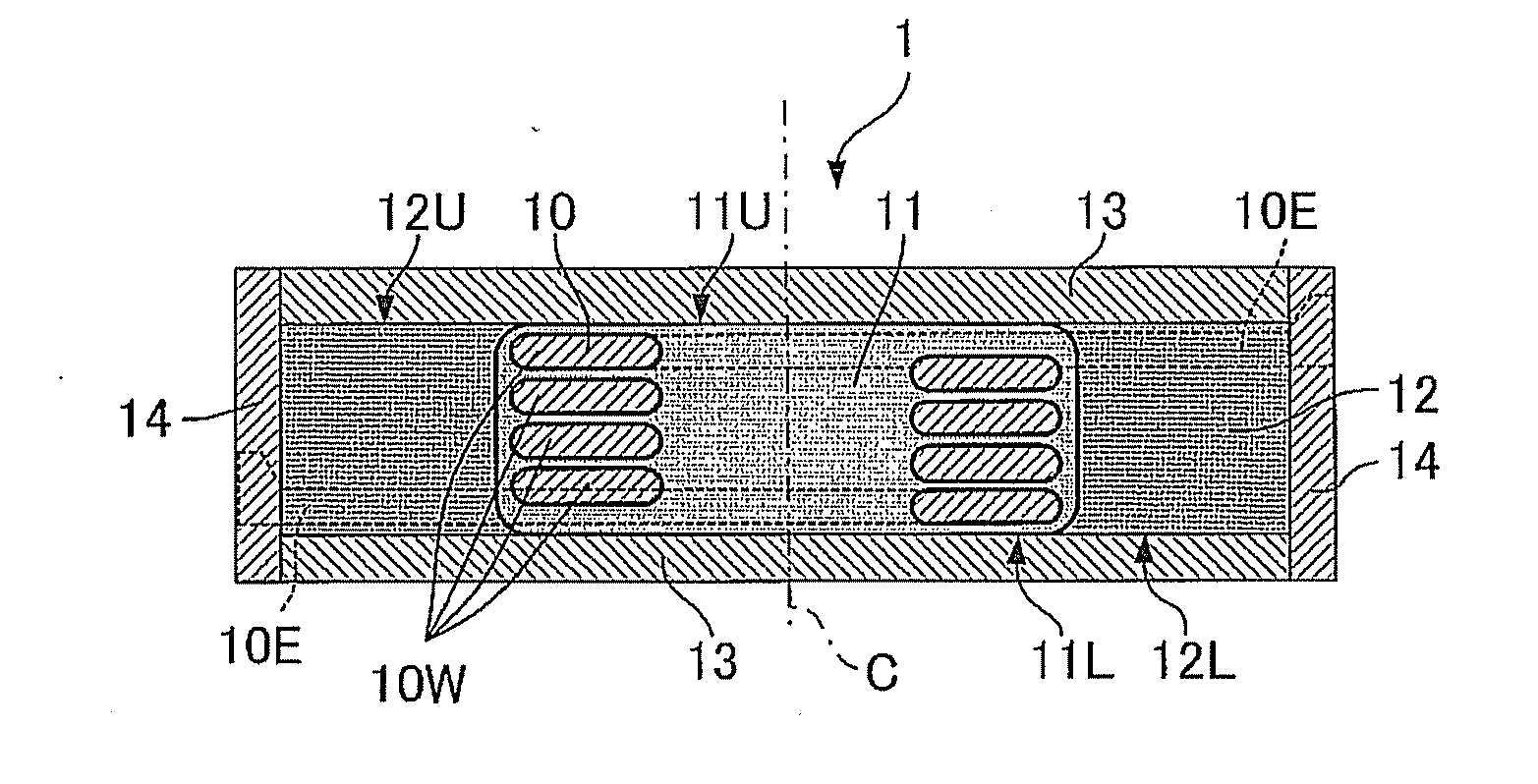
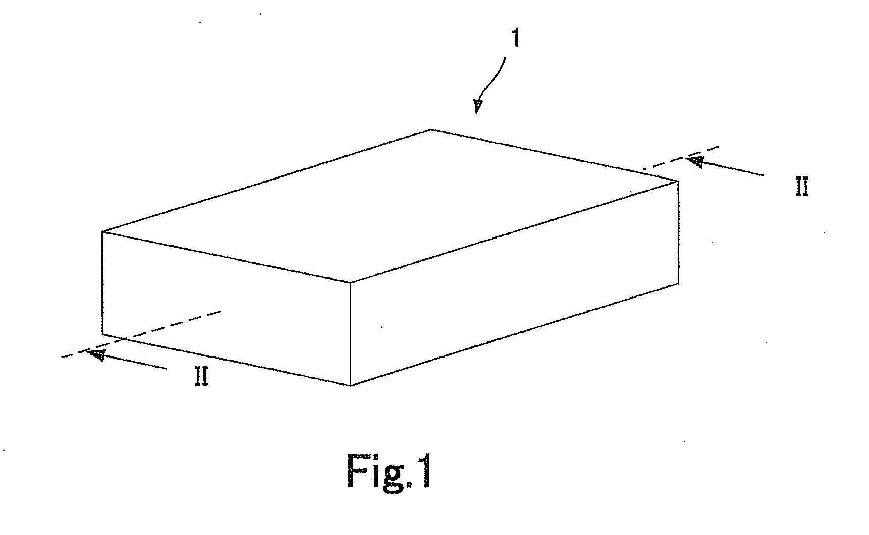
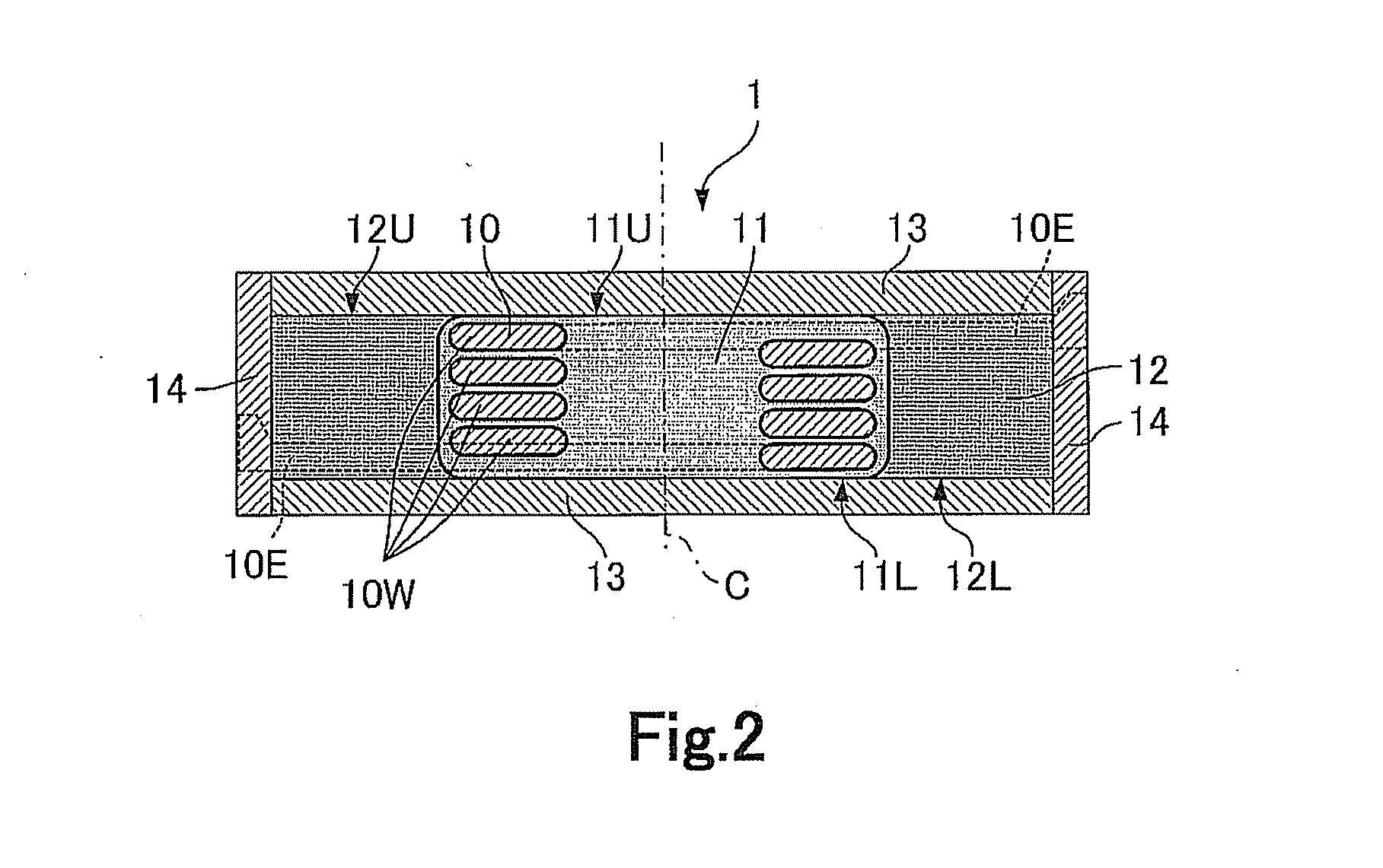
[0054]Below, the embodiment according to the present invention will be explained with referring to the drawings. In FIGS. 1 and 2, the coil-buried type inductor of the embodiment according to the present invention is shown. FIG. 1 is a perspective view of the coil-buried type inductor and FIG. 2 is a longitudinal sectional view of the coil-buried type inductor. In FIGS. 1 and 2, reference number 1 denotes the coil-buried type inductor, 10 denotes a coil, 11 denotes a first fired ceramics body, 12 denotes a second fired ceramics body, 13 denotes third fired ceramics bodies and 14 denotes outer electrode layers.

[0055]As shown in FIGS. 3 and 4, the coil 10 is a coil constituted by a wire material which is wound (turned) helically at a constant pitch P. Further, as can be understood from FIG. 2, the transverse cross sectional shape of the wire material which constitutes the coil 10 except the end portions 10E of the wire material of the coil 10, is generally rectangular and the transver...


PUM

PropertyMeasurementUnit
porosityaaaaaaaaaa
porosityaaaaaaaaaa
porosityaaaaaaaaaa

Abstract

The invention relates to a coil-buried type inductor. The inductor comprises a conductive coil, a first fired ceramics body arranged at least in an area along an inner periphery of the coil, and a second fired ceramics body arranged so as to surround the entire of the coil along with the first fired ceramics body. The first fired ceramics body has porosity equal to or larger than 40 percent and smaller than 70 percent.

Description

FIELD OF THE INVENTION[0001]The present invention relates to a coil-buried type inductor and a method for manufacturing the same.BACKGROUND ART[0002]A coil-buried type inductor is described in the Examined Japanese Patent Publication No. 3,248,463. The inductor described herein is constituted by a metallic coil, a resin which coats the coil and a ceramics compact which houses the coil coated by the resin. That is, the inductor described in the Publication is in the form of the coil coated by the resin being buried in the ceramics material. The inductor described in the Publication is manufactured as follows. That is, first, a coil is prepared and a resin coating material is coated on the coil such that the material surrounds the coil. Next, a ceramics slurry is provided around the coil coated by the coating material and then is hardened and thereby an unfired ceramics compact (hereinafter, this unfired ceramics compact will be simply referred to as “ceramics compact”) which has the ...

Claims


Application Information

Patent Timeline
Patent Type & Authority Applications(United States)
IPC IPC(8): H01F27/02H01F41/04
CPCH01F17/04Y10T29/4902H01F2017/048H01F41/0246
Inventor TAKEUCHI, KATSUYUKISHIMOGAWA, NATSUMIOZAWA, SHUICHI
Owner NGK INSULATORS LTD
Why Eureka
Try Eureka