Near-field optical head and information recording/reproducing device

a near-field optical head and information recording/reproducing technology, applied in combination recording, data recording, instruments, etc., can solve the problems of thermal demagnetization, inversion or loss of recorded information, loss of recorded information or the like, etc., and achieve the effect of efficiently generating a strong magnetic field and efficient generating near-field ligh

Inactive Publication Date: 2011-05-26
SEIKO INSTR INC
View PDF4 Cites 5 Cited by
  • Summary
  • Abstract
  • Description
  • Claims
  • Application Information

AI Technical Summary

Benefits of technology

[0032]In view of the foregoing, it is an object of the present invention to provide a near-field optical head that can efficiently generate near-field light while being compact and that can efficiently generate a strong magnetic field.

Problems solved by technology

When this bit size is reduced, the potential energy of the state in which one bit information is recorded becomes close to the thermal energy at room temperature, which may cause a thermal demagnetization problem in which, for example, recorded information is inverted or lost due to thermal fluctuation or the like.
However, this method may easily cause the loss of recorded information or the like due to the above-described thermal demagnetization.
Information recorded with a perpendicular magnetic field tends to keep stable in energy, because it is difficult for the north pole and the south pole to form a loop on the surface of the recording film.
This makes it difficult to record information to the recording medium even if the above-described perpendicular recording method is used.

Method used


Image

  • Near-field optical head and information recording/reproducing device
  • Near-field optical head and information recording/reproducing device
  • Near-field optical head and information recording/reproducing device

Examples


embodiment 1

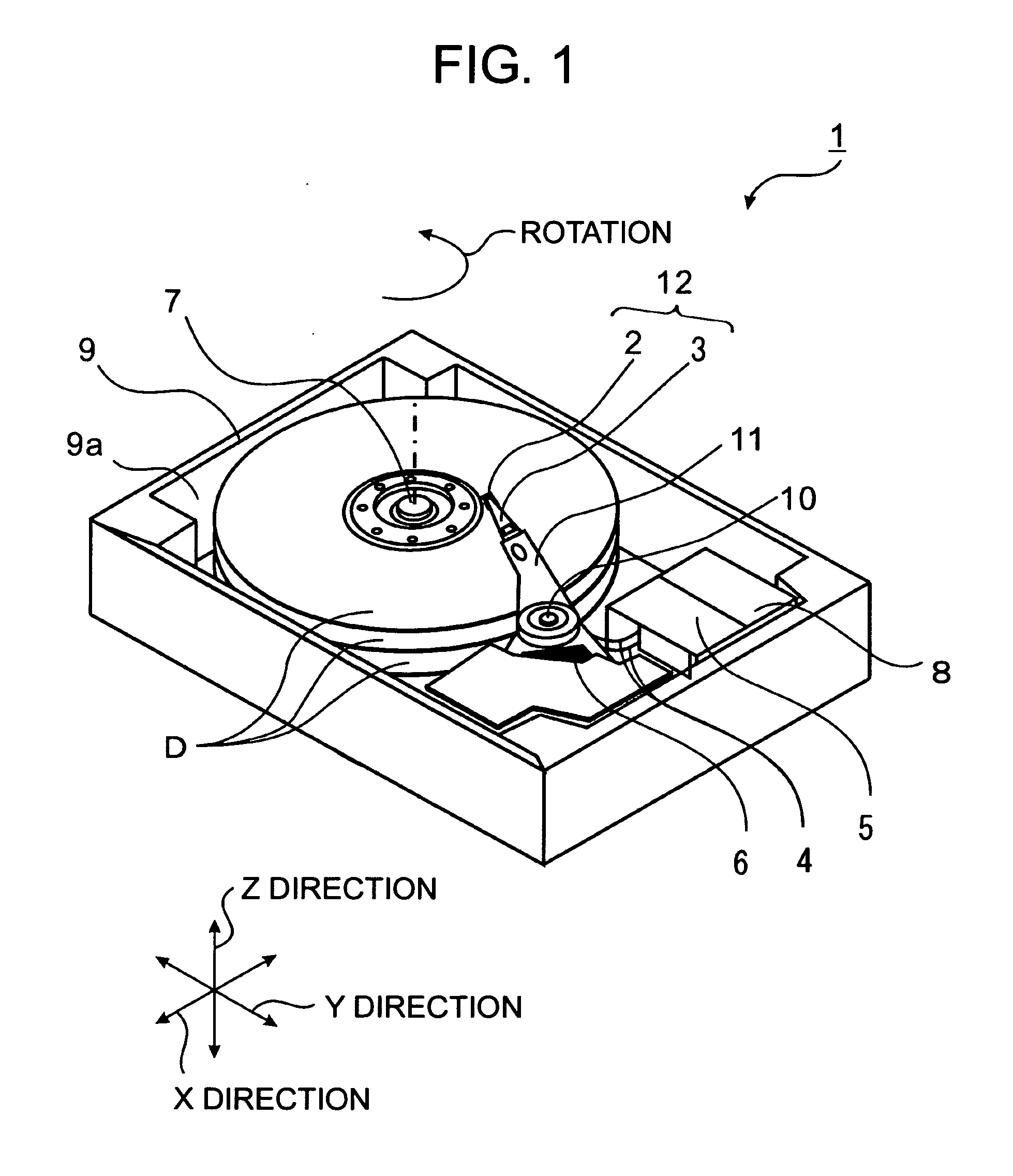
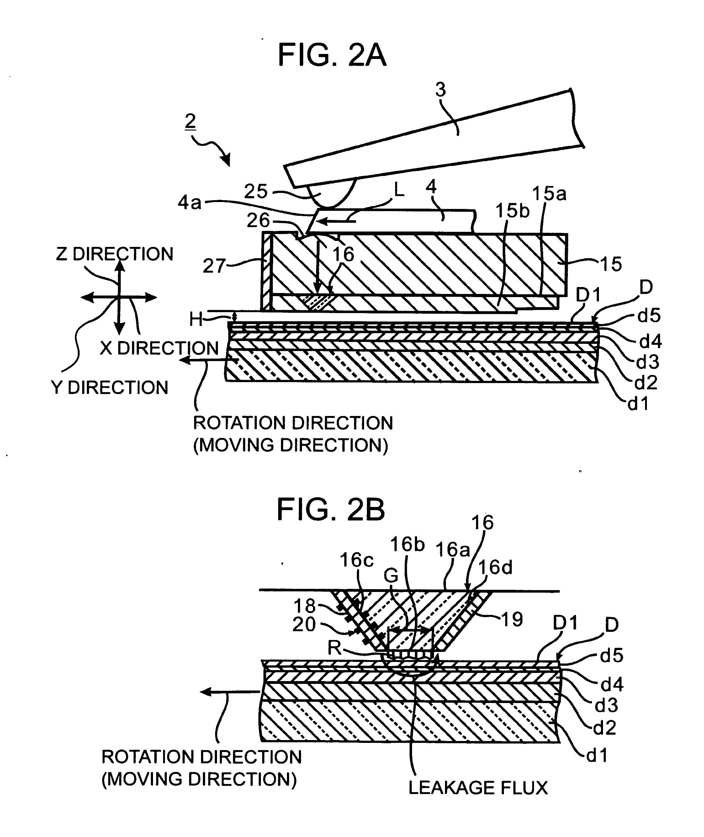
[0049]A first embodiment of a near-field optical head and an information recording / reproducing device in accordance with the present invention is described below with reference to FIGS. 1 to 6. It should be noted that an information recording / reproducing device 1 in accordance with the embodiment is described taking the case of writing to a disk (magnetic recording medium) D including a magnetic recording layer d3 using an in-plane recording method as an example.

[0050]FIG. 1 is a schematic view of the information recording / reproducing device 1 in accordance with the embodiment. The information recording / reproducing device 1 includes: a near-field optical head 2; a beam 3 for supporting the near-field optical head 2 at the tip of the beam 3, the beam 3 being able to move in X and Y directions parallel to the surface of the disk D (the surface of the magnetic recording medium), and being able to rotate about two axes (X-axis, Y-axis) that are parallel to the surface of the disk D and ...

embodiment 2

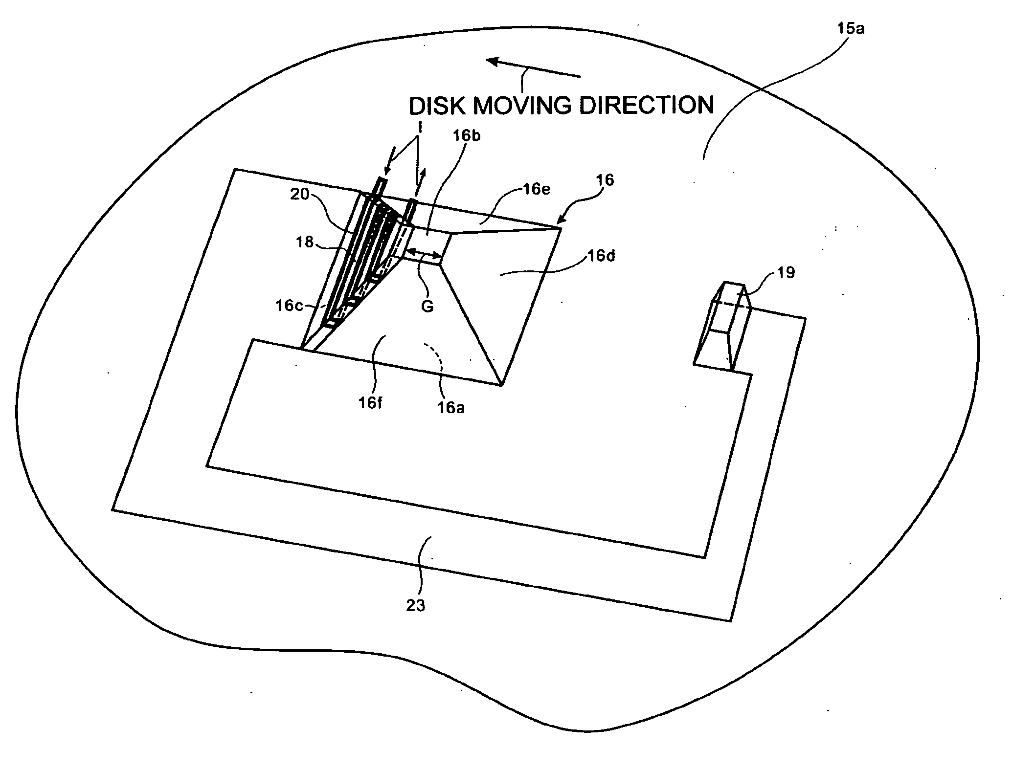
[0101]Next, a second embodiment of the near-field optical head in accordance with the invention is described with reference to FIGS. 7(a), 7(b), and 7(c). FIG. 7(a) shows a structure of a coil and a coil 20′ wound around magnetic poles 18 and 19, respectively. FIG. 7(b) is a plan view of FIG. 7(a). FIG. 7(c) is a cross-sectional view along the line A-A′ in FIG. 7(b). Note that, in the second embodiment, the same components as those in the first embodiment are given the same reference numerals and not repeatedly described here.

[0102]In FIGS. 4 and 5, the coil is wound around one of the magnetic poles 18 and 19. In contrast, in FIG. 7, coils are wound around both of the magnetic poles 18 and 19, and not only the magnetic pole 18 and the coil 20 but the magnetic pole 19 and the coil 20′ form an electromagnet as a whole.

[0103]In comparison with the structure shown in FIGS. 4 and 5, by winding the coil 20 and 20′ around the magnetic poles 18 and 19, respectively, stronger leakage magneti...

embodiment 3

[0106]Next, a third embodiment of the near-field optical head in accordance with the invention is described with reference to FIGS. 8(a) and 8(b). FIG. 8(a) shows an example of the case that a core 16 is a truncated square pyramid. FIG. 8(b) shows an example of the case that a core 16 is a truncated triangular pyramid. Note that, in the third embodiment, the same components as those in the first and second embodiments are given the same reference numerals and not repeatedly described here.

[0107]In FIGS. 4 and 5 or in FIG. 7, the magnetic poles 18 and 19 are formed on the side surfaces 16c and 16d of the core 16, respectively. In contrast, the structure shown in FIGS. 8(a) and 8(b) is what is called a single-pole structure, in which only a magnetic pole 18 is formed as main magnetic pole on a side surface 16c of the core 16, and a coil is wound around the magnetic pole 18. A magnetic pole 19′ functioning as the auxiliary magnetic pole is provided on a counter surface 15a on which a c...


PUM

PropertyMeasurementUnit
magnetic fieldaaaaaaaaaa
heightaaaaaaaaaa
magneticaaaaaaaaaa

Abstract

A near-field optical head includes: a near-field light generating element, formed on a counter surface of a slider facing the surface of a magnetic recording medium and having two or more side surfaces each of which are in contact with the counter surface at a certain angle with the counter surface, for generating the near-field light; at least one lower wiring formed on at least one of the side surfaces of the near-field light generating element; a thin-film-like magnetic pole disposed to a position covering the lower wiring; at least one upper wiring disposed on one of the two sides of the magnetic pole, opposite to the side on which the lower wiring is disposed; at least one side surface wiring connecting the lower wiring and the upper wiring; insulating layers insulating each of the lower wiring, the magnetic pole, and the upper wiring from the others; and a coil wound around the magnetic pole by connecting the lower wiring and the upper wiring alternately and serially using the side surface wiring.

Description

TECHNICAL FIELD[0001]The present invention relates to a near-field optical head and an information recording / reproducing device having the near-field optical head that can record various information to a magnetic recording medium at ultrahigh density using near-field light.BACKGROUND ART[0002]In recent years, storage capacity of a hard disk and the like in a computer apparatus has increased, which has increased the density of information recording on a single recording surface. For example, in order to increase the recording capacity in a magnetic disk, the surface recording density needs to be increased. However, as the recording density increases, the recording area occupied by one bit on the recording medium decreases. When this bit size is reduced, the potential energy of the state in which one bit information is recorded becomes close to the thermal energy at room temperature, which may cause a thermal demagnetization problem in which, for example, recorded information is inver...

Claims


Application Information

Patent Timeline
Patent Type & Authority Applications(United States)
IPC IPC(8): G11B13/04
CPCG11B5/314G11B2005/0021G11B2005/001G11B5/6088
Inventor PARK, MAJUNGOUMI, MANABUHIRATA, MASAKAZU
Owner SEIKO INSTR INC
Why Eureka
Try Eureka