
Vein scanner

a scanner and vein technology, applied in the field of vein scanners, can solve the problems of extreme discomfort of patients, medical professionals may still not be able to find an appropriate vein, and the conventional methods of performing these procedures have several limitations, so as to achieve convenient access, improve patient comfort, and improve the effect of venipucture flow

Active Publication Date: 2011-05-26
ACCUVEIN
View PDF99 Cites 55 Cited by
  • Summary
  • Abstract
  • Description
  • Claims
  • Application Information

AI Technical Summary

Benefits of technology

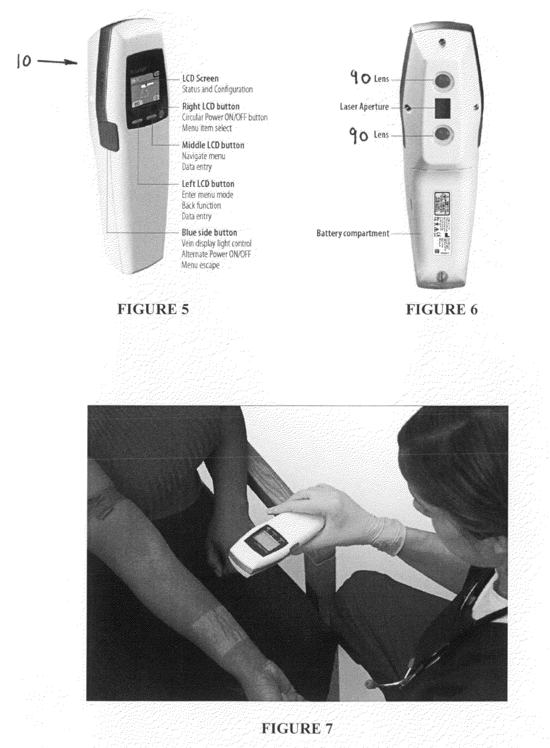
[0003]The present invention is directed towards a portable hand-held medical apparatus that uses infrared light to detect veins beneath the skin, then illuminating the position of the veins on the skin surface directly above the veins using visible light. When the apparatus is held a distance above the outer surface of the skin, veins appear vastly different than the surrounding tissue, and veins that are otherwise undetectable because of their depth in the tissue are safely located and mapped on the patient's skin. Vein's will be accessed more readily and with greater confidence and as such, venipuctures will go more smoothly while vasculature shows up clearly on the skin's surface, making it easy to select the best vein to collect a blood sample from or administer medications to. Qualified medical personnel can observe the displayed vasculature to assist them in finding a vein of the right size and position for venipuncture.

Problems solved by technology

Drawing blood and administering intravenous medication using medical devices including but not limited to catheters are common medical procedures, but conventional methods to perform these procedures have several limitations.
This is often accomplished by the use of a temporary tourniquet, which can result in extreme discomfort to the patient.
Even after the temporary tourniquet is applied and certain veins are exposed, a medical professional may still not be able to find an appropriate vein.
This problem can occur more readily in elderly patients and patients with low blood pressure.

Method used


Image

  • Vein scanner
  • Vein scanner
  • Vein scanner

Examples


Embodiment Construction

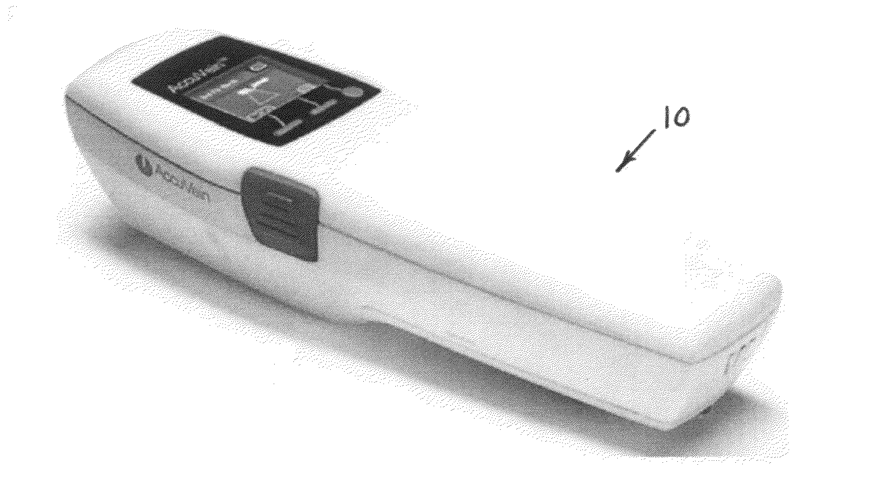
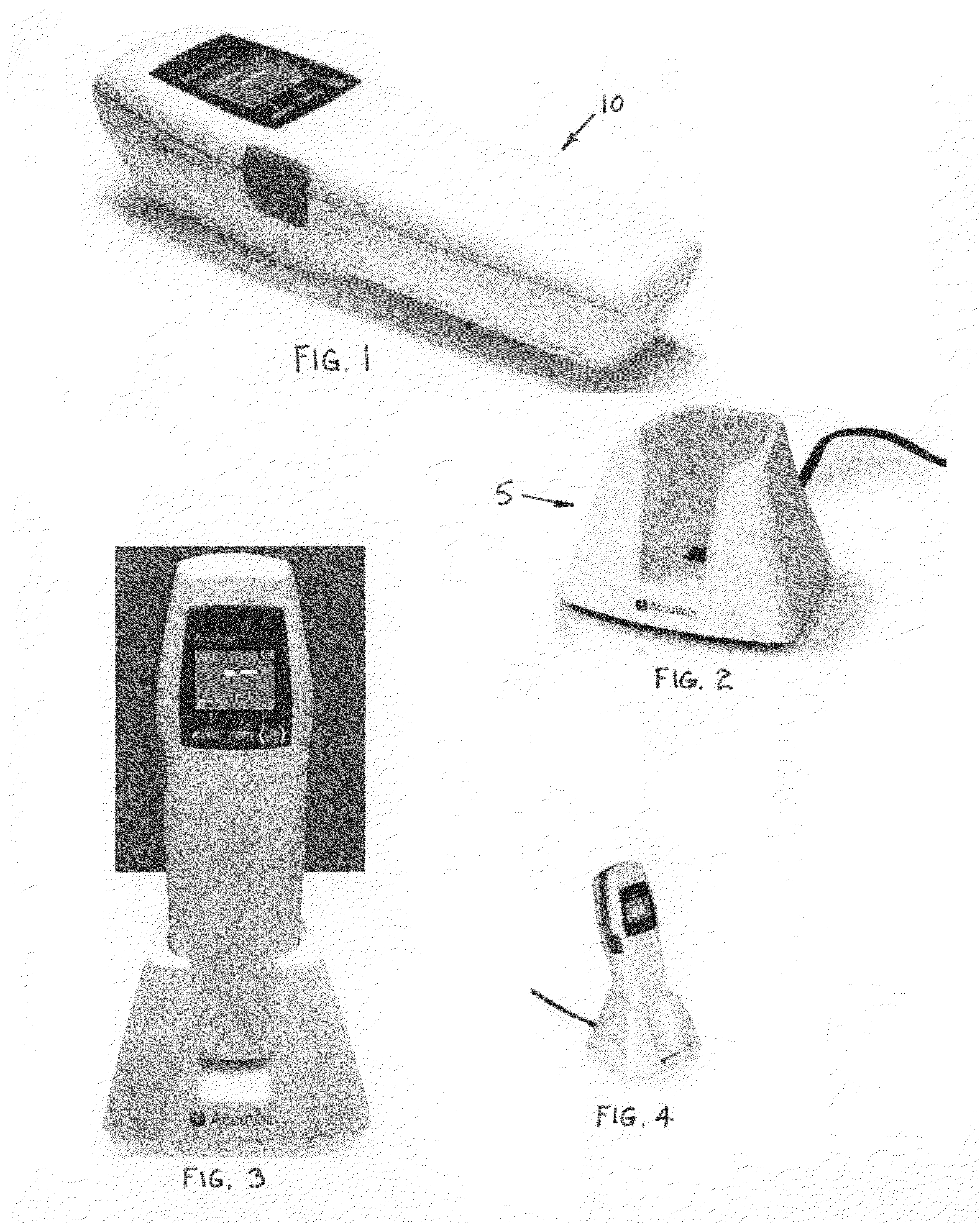
[0084]The present invention is directed to an apparatus 10 (FIG. 1) that is an opto-electronic device that assists medical practitioners by locating veins and then projecting an image of those veins directly on a patient's skin. The apparatus may be portable, hand held, and battery powered. However in an alternative embodiment an external power supply may be used to power the apparatus. The apparatus operates by using infrared light to detect veins beneath the skin, and then illuminates the position of the veins on the skin surface directly above the veins using visible light. The apparatus 10 may be battery powered, and rechargeable using a cradle 5 (FIG. 2), and may generally be stored therein (FIGS. 3-4).

[0085]The apparatus 10 generally comprises a housing 11, internal circuitry 12, keypad 13, display 14, scanner assembly 15, and battery pack 16. The housing 11 may generally comprise a top section 17 and bottom section 18 as shown in FIG. 30. Although a specific shape for the hou...


PUM


Abstract

A portable vein viewer apparatus may be battery powered and hand-held to reveal patient vasculature information to aid in venipuncture processes. The apparatus comprises a first laser diode emitting infrared light, and a second laser diode emitting only visible wavelengths, wherein vasculature absorbs a portion of the infrared light causing reflection of a contrasted infrared image. A pair of silicon PIN photodiodes, responsive to the contrasted infrared image, causes transmission of a corresponding signal. The signal is processed through circuitry to amplify, sum, and filter the outputted signals, and with the use of an image processing algorithm, the contrasted image is projected onto the patient's skin surface using the second laser diode. Revealed information may comprise vein location, depth, diameter, and degree of certainty of vein locations. Projection of vein images may be a positive or a negative image. Venipuncture needles may be coated to provide visibility in projected images.

Description

CROSS REFERENCES TO RELATED APPLICATIONS[0001]This application claims priority on U.S. Provisional Application Ser. No. 61 / 271,587 filed on Jul. 22, 2009, the disclosures of which are incorporated herein by reference.BACKGROUND OF THE INVENTION[0002]Drawing blood and administering intravenous medication using medical devices including but not limited to catheters are common medical procedures, but conventional methods to perform these procedures have several limitations. First a vein must be found. Conventional methods of locating an appropriate vein or artery include restricting the blood supply to the location of the body so that the blood pressure in that area is greater, which results in the patient's veins becoming more visible. This is often accomplished by the use of a temporary tourniquet, which can result in extreme discomfort to the patient. Even after the temporary tourniquet is applied and certain veins are exposed, a medical professional may still not be able to find an...

Claims


Application Information

Patent Timeline
IPC IPC(8): A61B6/00
CPCA61B5/0064A61B5/02007A61B5/489A61B5/7239A61B2560/0431A61B2560/0456A61B2560/0425
Inventor WOOD, FREDLUCIANO, VINCENTGOLDMAN, RON
Owner ACCUVEIN
Learn More