Tetherless tube inspection system

a technology of inspection system and bobbin, which is applied in the direction of instruments, nuclear elements, greenhouse gas reduction, etc., can solve the problems of affecting the centering of the probe or its forward progress, and affecting the stability of the prob

Inactive Publication Date: 2011-05-26
WESTINGHOUSE ELECTRIC CORP
View PDF15 Cites 33 Cited by
  • Summary
  • Abstract
  • Description
  • Claims
  • Application Information

AI Technical Summary

Benefits of technology

[0014]These and other objects are achieved by the nondestructive inspection probe system of this invention which basically includes a nondestructive inspection sensor sized to movably fit within the tubing to be inspected, with the inspection sensor having one of either a male or female disconnectable coupling. The nondestructive inspection probe system of this invention further includes an electronics module sized to movably fit within the tubing with the electronics module having the other of either the male or female disconnectable coupling which is adapted to connect to the one of either the male or female disconnectable coupling on the inspection sensor and when so connected to electrically communicate with the nondestructive inspection sensor. The electronics module is so configured to move within the tubing along with the nondestructive sensor, while receiving data from the sensor without any tethering extending outside the interior of the tubing. The electronics module preferably includes a memory for storing the data from the nondestructive inspection sensor and desirably, the data is communicated from the electronics module memory to a data collection center at the end of the inspection of each tube. Desirably, the electronics module includes a control for adjusting the speed of movement of the nondestructive inspection sensor within the tubing. In one embodiment, the control for adjusting the speed controls a drag of the nondestructive inspection sensor on the interior of the tubing.

Problems solved by technology

In the past, steam generator tubing in nuclear plants have been exposed to extreme operating conditions and were susceptible to stress corrosion cracking, mechanical wear, wall thinning and pitting.
Although widely and relatively successfully used, the relatively rigid Bobbin-type probes are difficult to push through tubes that have bends.
Side loads developed by the pushing shaft as the probe traverses bends in the tubing and to a lesser extent side loads due to off center shaft positioning in the straight lengths can adversely impact the centering of the probe or its forward progress.
Furthermore, existing inspection equipment is bulky and the long flexible shaft that is used to push the inspection probe through the length of the tubes becomes highly contaminated.
Additionally, the shaft is subject to buckling, which causes difficulties during the inspection operation.

Method used


Image

  • Tetherless tube inspection system
  • Tetherless tube inspection system
  • Tetherless tube inspection system

Examples


Embodiment Construction

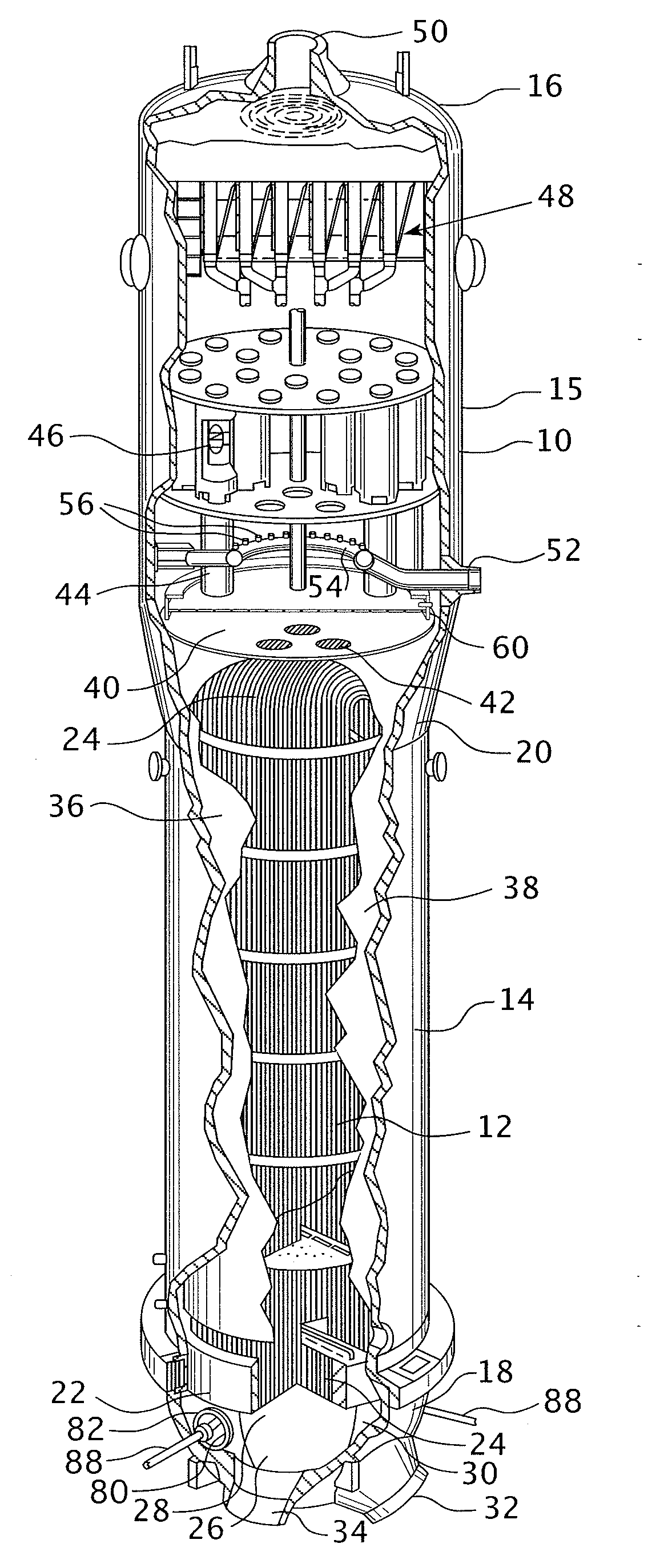
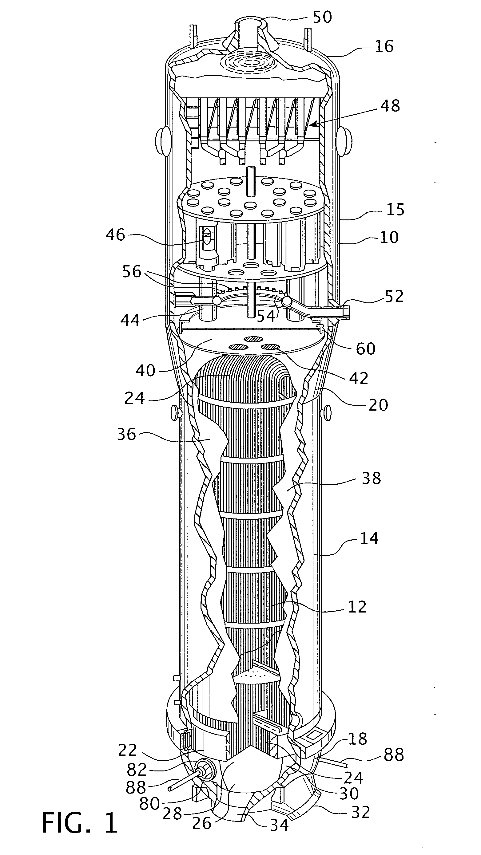
[0024]Referring to the drawings, FIG. 1 shows a steam or vapor generator 10 that utilizes a plurality of U-shaped tubes which form a tube bundle 12 to provide the heating surface required to transfer heat from a primary fluid traveling within the tubes to vaporize or boil a secondary fluid surrounding the outside of the tubes. The steam generator 10 comprises a vessel having a vertically oriented tubular shell having a lower reduced diameter portion 14, a conical center portion 20 and an enlarged diameter upper portion 15 that is capped by a top enclosure or dished head 16 enclosing the upper end and a generally hemispherical shaped channel head 18 enclosing the lower end. A tube sheet 22 is attached to the channel head 18 and has a plurality of holes disposed therein to receive the ends of the U-shaped tubes. A dividing plate 26 is centrally disposed within the channel head 18 to divide the channel head into two compartments 28 and 30, which serve as headers for the tube bundle 12....


PUM


Abstract

Apparatus and a method to inspect tubing by means of a free flying, autonomous inspection head that is not attached by wires to external control and data acquisition equipment. The inspection head travels through the tube with an attached module that integrates all the necessary support for the electronic and mechanical control of a nondestructive sensor within the inspection head.

Description

CROSS REFERENCE TO RELATED APPLICATION[0001]This application claims the priority of Provisional Application Ser. No. 61 / 178,190, filed May 14, 2009.BACKGROUND OF THE INVENTION[0002]1. Field of the Invention[0003]The present invention relates generally to nondestructive examination of heat exchanger tubing and more particularly to a tetherless self-contained inspection system that can traverse small tubing diameters.[0004]2. Related Art[0005]Steam generators used in nuclear power plants are very large heat exchangers where heat from a primary fluid heated by a nuclear reactor is transferred to a secondary fluid which is converted into steam and used to drive a turbine generator. Steam generators are housed inside a tall, generally cylindrical steel shell. A large number of U-shaped heat exchanger tubes are enclosed in the shell and have their ends inserted in holes formed in a horizontal tube sheet or plate near the bottom of the steel shell. The tubes are used to convey the primary ...

Claims


Application Information

Patent Timeline
Patent Type & Authority Applications(United States)
IPC IPC(8): G06F15/00G01D21/00
CPCF22B37/003G01N27/902Y02E30/40G21C17/017G21D1/006G01N29/265Y02E30/30Y02E30/00F16L55/48G01N27/82G01N29/11
Inventor PETROSKY, LYMAN J.BOYNTON, JAYNE L.LLOYD, KEITH B.
Owner WESTINGHOUSE ELECTRIC CORP
Why Eureka
Try Eureka