Communication system having a can bus and a method for operating such a communication system

a communication system and can bus technology, applied in the field of communication system having can bus and the operation method of the communication system having the can bus, can solve the problem of limited symbol rate of the maximum possible can bus at the moment, and achieve the effect of reducing the maximum symbol rate of the can bus at approximately 1 mbaud

Active Publication Date: 2011-05-26
ROBERT BOSCH GMBH
View PDF22 Cites 25 Cited by
  • Summary
  • Abstract
  • Description
  • Claims
  • Application Information

AI Technical Summary

Benefits of technology

[0004]A communication system according to an example embodiment of the present invention and a method according to an example embodiment of the present invention for operating a communication system may have the advantage that the devices connected with the aid of the CAN bus are suitable for transmitting, over the CAN bus, CAN data frames in a first transmission mode and ASC (Asynchronous Serial Communication) data frames in a second transmission mode.

Problems solved by technology

Furthermore, the maximum possible symbol rate of a CAN bus is currently limited to approximately 1 Mbaud due the physical boundary conditions and, in particular, due to asymmetric delays on the CAN bus.

Method used


Image

  • Communication system having a can bus and a method for operating such a communication system
  • Communication system having a can bus and a method for operating such a communication system
  • Communication system having a can bus and a method for operating such a communication system

Examples


Embodiment Construction

[0031]In the figures, the same reference numerals identify the same components or components having the same function.

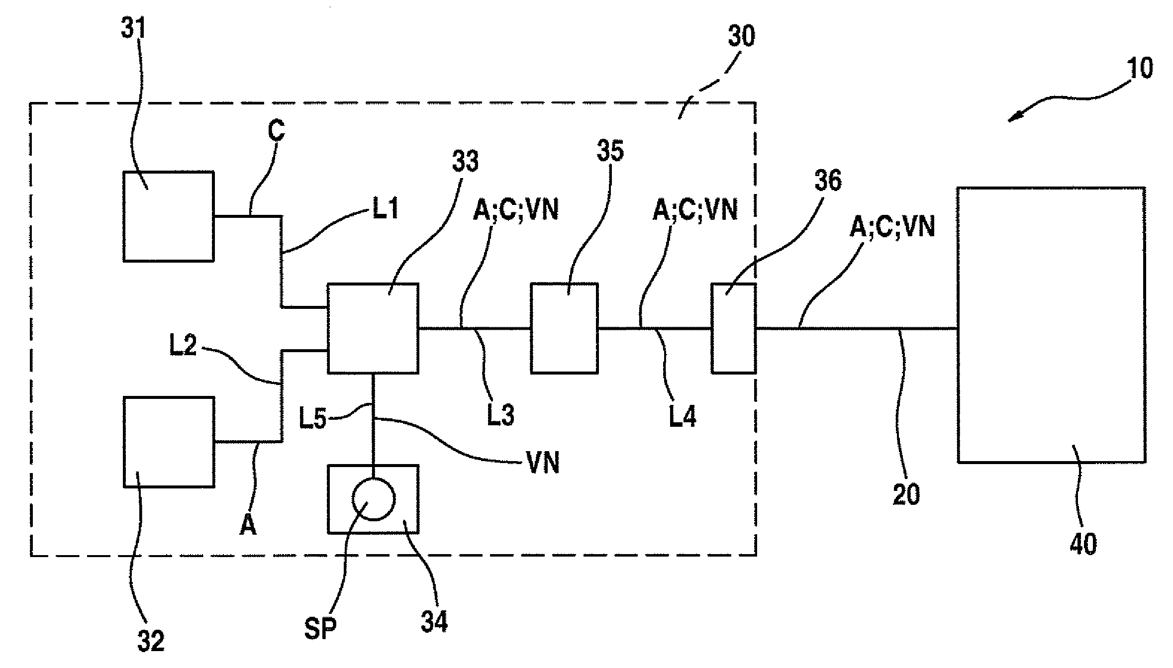
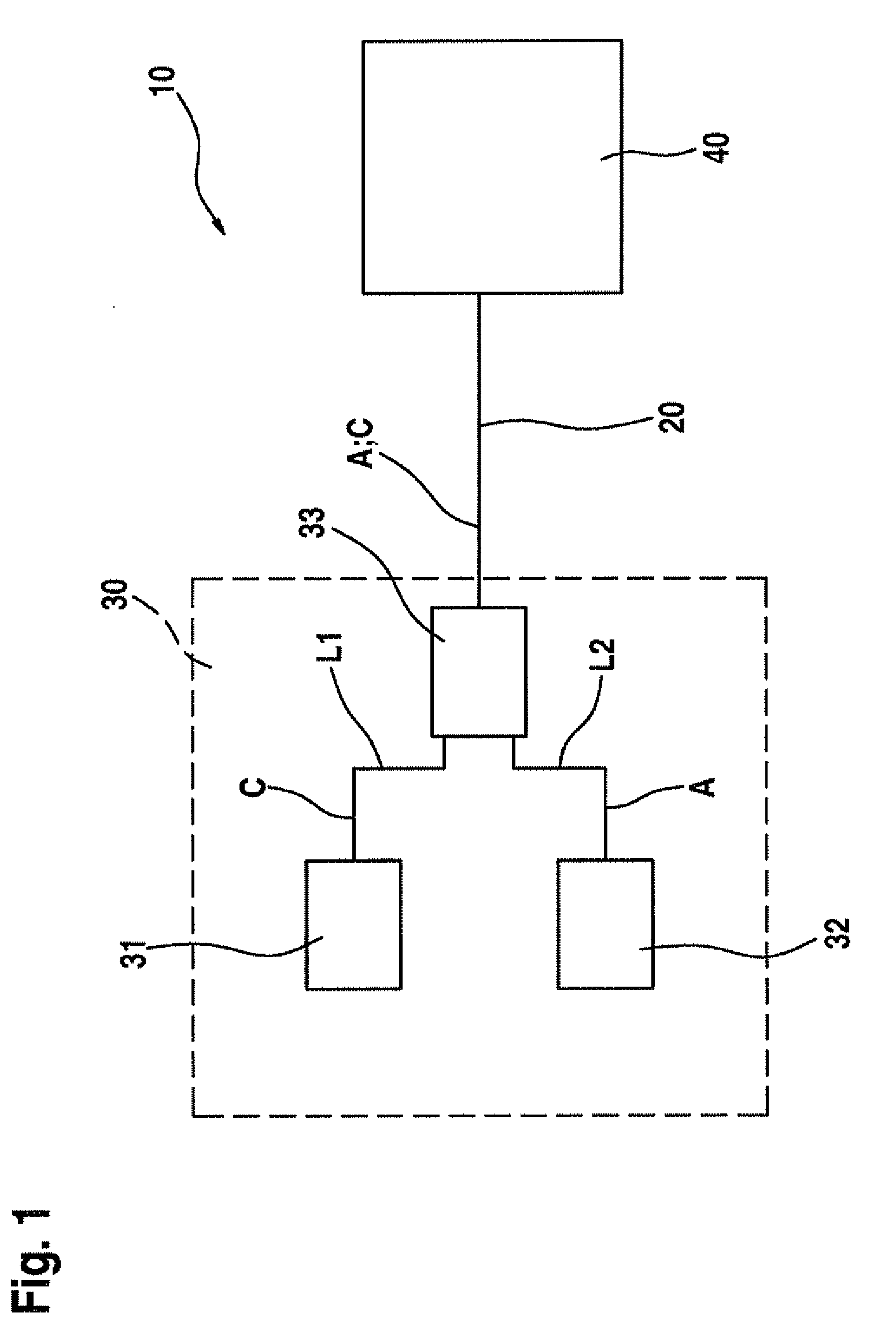
[0032]FIG. 1 shows a schematic block diagram of a first exemplary embodiment of a communication system 10 according to the present invention.

[0033]Communication system 10 has a CAN bus 20, at least two devices 30, 40 connected with the aid of CAN bus 20, and a switch 33.

[0034]The at least two devices 30, 40 connected with the aid of CAN bus 20 preferably include either a test device and at least one control device or at least two control devices. The test device is provided in a workshop for example. The control devices are preferably provided in a motor vehicle.

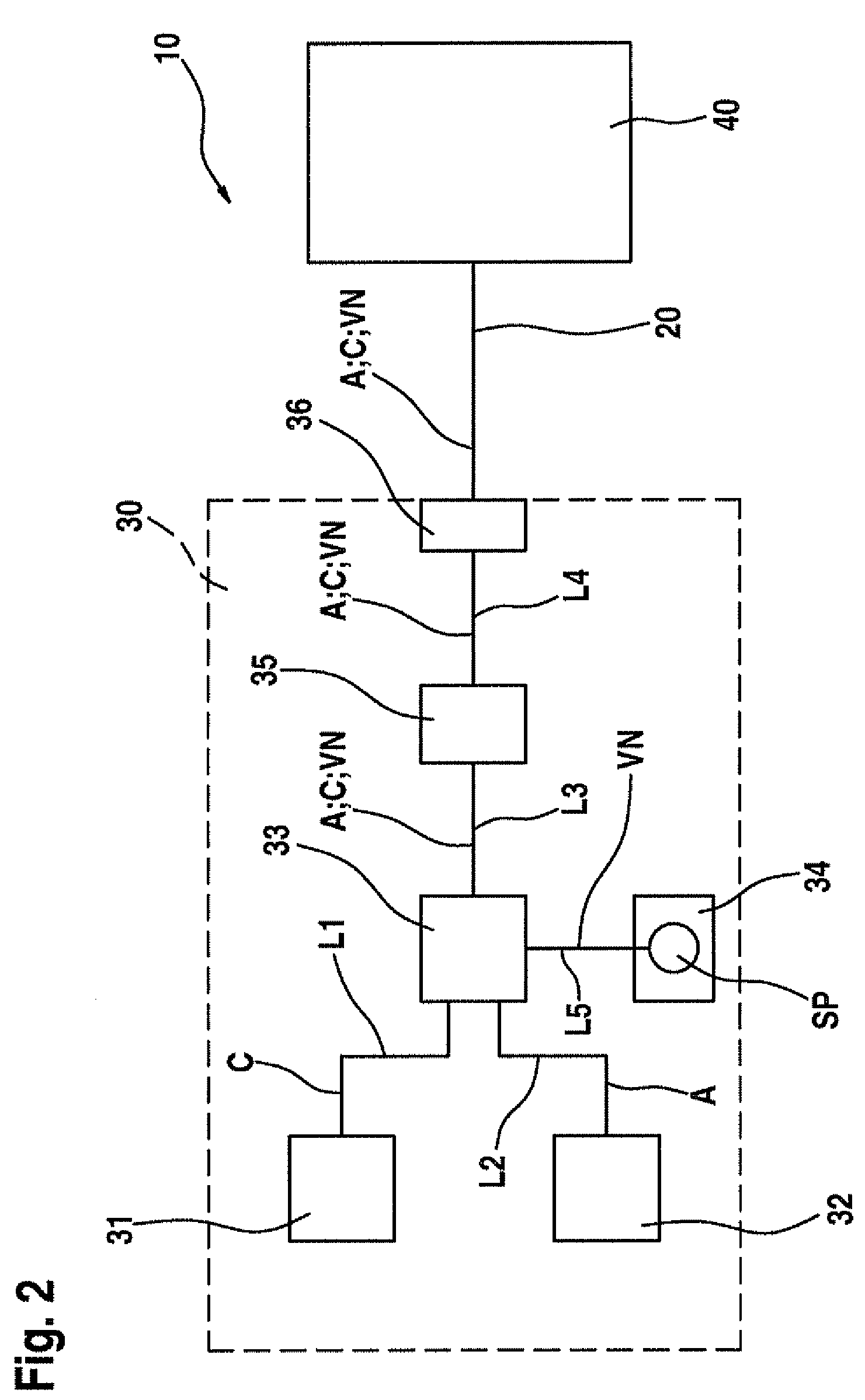
[0035]In FIGS. 1 and 2, reference numerals 30 and 40 denote, for example, two control devices which have an identical design.

[0036]For the sake of clarity, only first control device 30 is elucidated in detail. However, basically the same applies to second control device 40.

[0037]First control device 30 has a ...


PUM


Abstract

A communication system and a method for operating a communication system, the communication system having a CAN bus and at least two devices connected with the aid of the CAN bus. Such a device has a CAN control unit, an asynchronous, serial communication (ASC) interface unit, and a switch. The CAN control unit is suitable for transmitting, in a first transmission mode, CAN data frames over the CAN bus with the aid of a first physical protocol. The asynchronous, serial communication interface unit or ASC interface unit is suitable for transmitting, in a second transmission mode, ASC data frames over the CAN bus with the aid of a second physical protocol. The switch is designed for switching over between the first transmission mode and the second transmission mode as a function of at least one agreement effective between the device and at least one other device.

Description

FIELD OF THE INVENTION[0001]The present invention relates to a communication system having a CAN bus and a method for operating a communication system having a CAN bus.BACKGROUND INFORMATION[0002]In data transmission, in particular transmission of CAN messages using a CAN bus, the protocol overhead of the physical protocol associated with the CAN bus amounts to approximately 55%, i.e., the header part of the particular CAN message is greater than its useful data part or payload part.[0003]Furthermore, the maximum possible symbol rate of a CAN bus is currently limited to approximately 1 Mbaud due the physical boundary conditions and, in particular, due to asymmetric delays on the CAN bus.SUMMARY[0004]A communication system according to an example embodiment of the present invention and a method according to an example embodiment of the present invention for operating a communication system may have the advantage that the devices connected with the aid of the CAN bus are suitable for ...

Claims


Application Information

Patent Timeline
Patent Type & Authority Applications(United States)
IPC IPC(8): G06F13/42
CPCH04L2012/40215H04L12/40032
Inventor AUE, AXELGRUENEWALD, MARTIN
Owner ROBERT BOSCH GMBH
Why Eureka
Try Eureka