Apparatus for automatic control of exhaust pressure of an internal combustion engine

an internal combustion engine and automatic control technology, applied in the direction of engine controllers, machines/engines, mechanical apparatus, etc., can solve the problems of increasing the exhaust pressure of the engine, consuming more fuel than is necessary, reducing the output of the engine, etc., to increase the exhaust pressure, reduce the exhaust fume, and increase the efficiency of fuel combustion

Inactive Publication Date: 2011-06-02
JANG KEUN JIN
View PDF1 Cites 1 Cited by
  • Summary
  • Abstract
  • Description
  • Claims
  • Application Information

AI Technical Summary

Benefits of technology

[0015]With an apparatus for automatic control of exhaust pressure of an internal combustion engine according to an embodiment of the present invention, the amount by which the exhaust passage is opened and closed can be controlled automatically, to increase exhaust pressure during low-speed rotation and lower exhaust pressure during high-speed rotation, and thus effectively correspond to the valve overlap, thereby optimizing the exhaust pressure by immediately responding to the change in output of the internal combustion engine, that is to say, the change in rotational speed. This can increase the efficiency of fuel combustion, thus substantially decreasing exhaust fumes and saving fuel costs, and can increase rotational torque not only during high-speed movement but also during low-speed movement, thus enhancing stability in movement.
[0016]The apparatus can also be easily attached to and detached from an existing exhaust pipe installed in a vehicle, has a low rate of failure from having a simple structure, can be installed conveniently, and has a low cost of production.
[0017]Also, according to an embodiment of the present invention, since the amount by which the exhaust passage is opened and closed is automatically controlled according to the running speed of the vehicle by using the drag generated by a pendulum blade, a driver may drive a vehicle with maximum engine efficiency without paying particular attention
[0018]Furthermore, an apparatus for automatic control of exhaust pressure of an internal combustion engine according to an embodiment of the present invention also has the marked effect of creating an optimal exhaust pressure environment by conforming easily to various sizes of exhaust pipes installed in a variety of vehicles, as the initial gradient setting of the pressure control plate and the control of the vertical position of the pendulum blade can be easily handled.

Problems solved by technology

However, when an internal combustion engine is running at a high speed, because the piston is making an alternating motion at a very fast speed, a high exhaust pressure can actually be an obstacle to the lift of the piston in the last stage of the valve overlap.
Thus, a great deal of fuel is incompletely combusted and exhausted during the valve overlap, causing the engine's output to decrease.
In other words, the exhaust system of an internal combustion engine according to the related art does not include a means to adjust the exhaust pressure to the output of the internal combustion engine in correspondence with the valve overlap, because it uses an exhaust pipe of a fixed size, and thus has the problem of consuming more fuel than is necessary and of decreasing the engine's output, especially during low-speed rotation.
These methods, however, do not entail simple structures and require the replacement of the entire exhaust pipe for installation, and in particular, substantially increases cost due to additional attachments such as a detector sensor.

Method used


Image

  • Apparatus for automatic control of exhaust pressure of an internal combustion  engine
  • Apparatus for automatic control of exhaust pressure of an internal combustion  engine
  • Apparatus for automatic control of exhaust pressure of an internal combustion  engine

Examples


Embodiment Construction

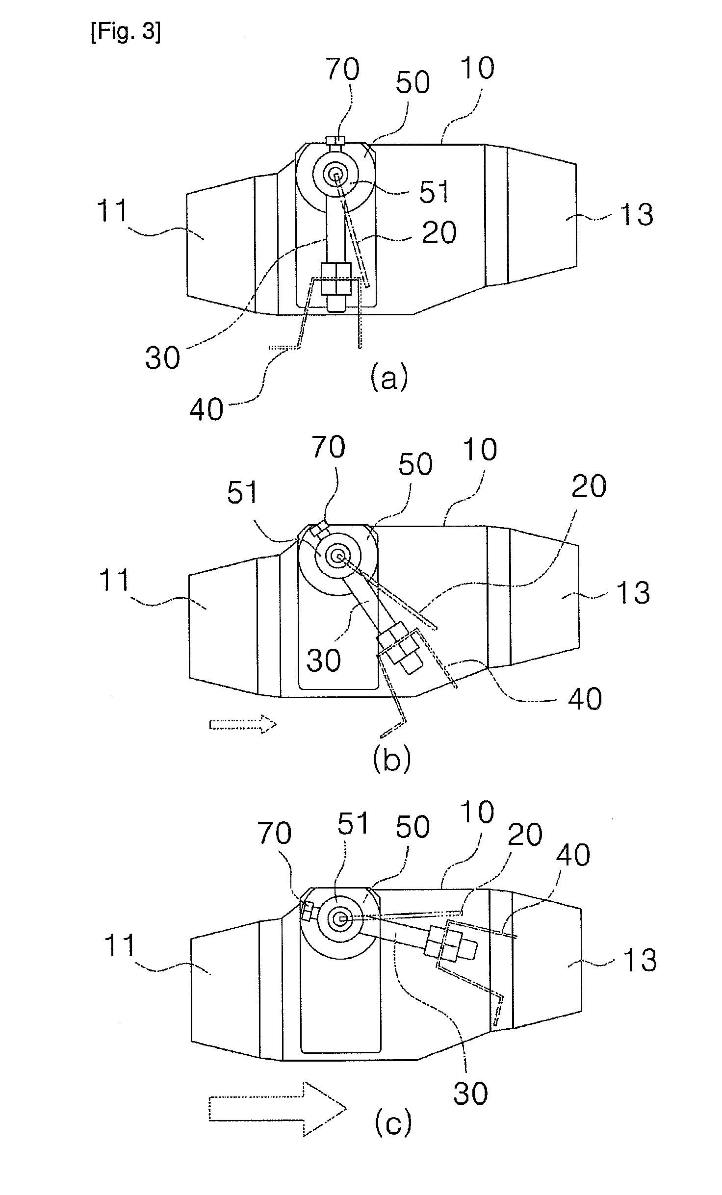
[0022]An apparatus for automatic control of exhaust pressure of an internal combustion engine according to an embodiment of the present invention is designed to automatically control the amount by which the exhaust passage is opened and closed according to the exhaust pressure, automatically increasing the exhaust pressure during low-speed rotation and lowering the exhaust pressure during high-speed rotation, and thus effectively responding to the valve overlap.

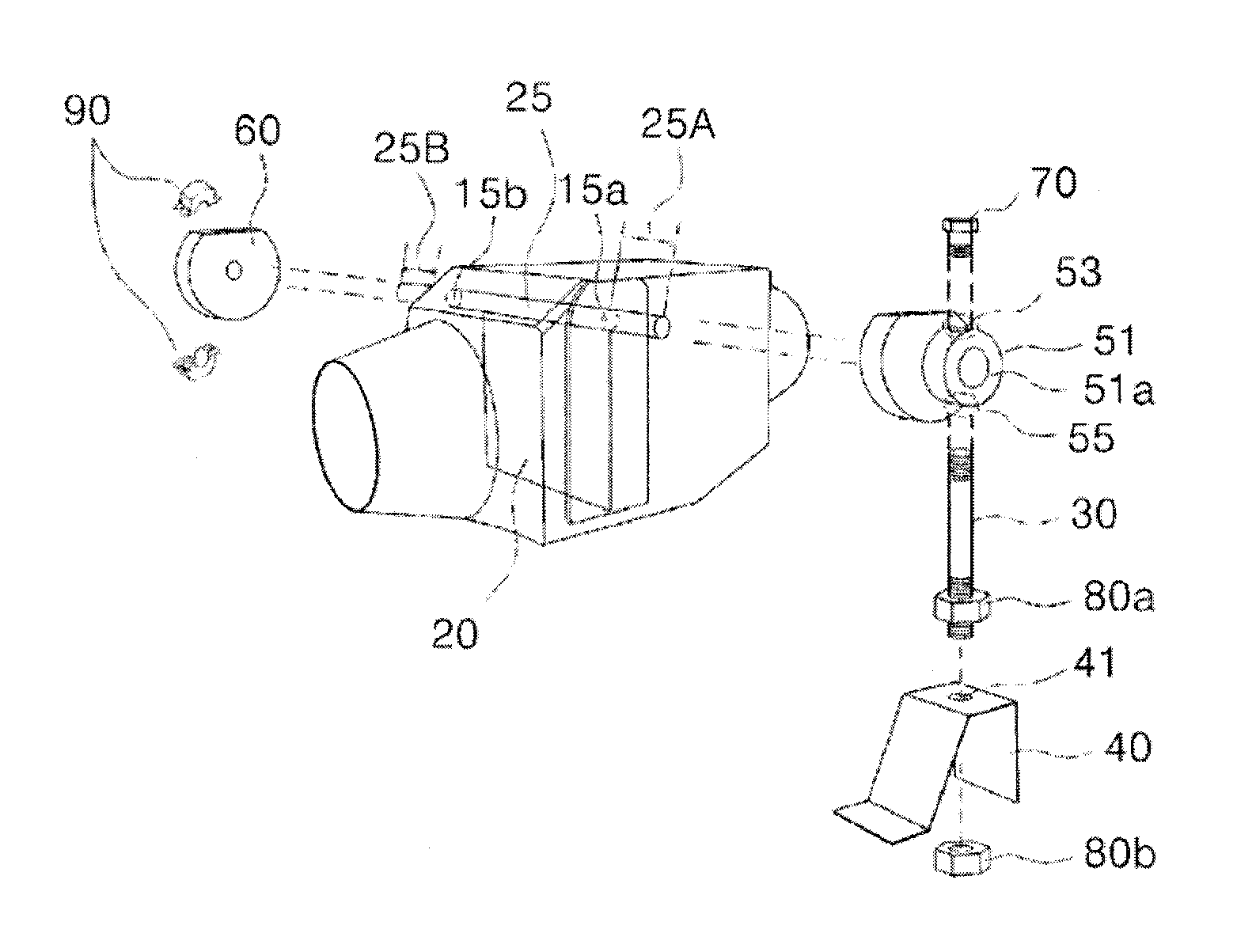
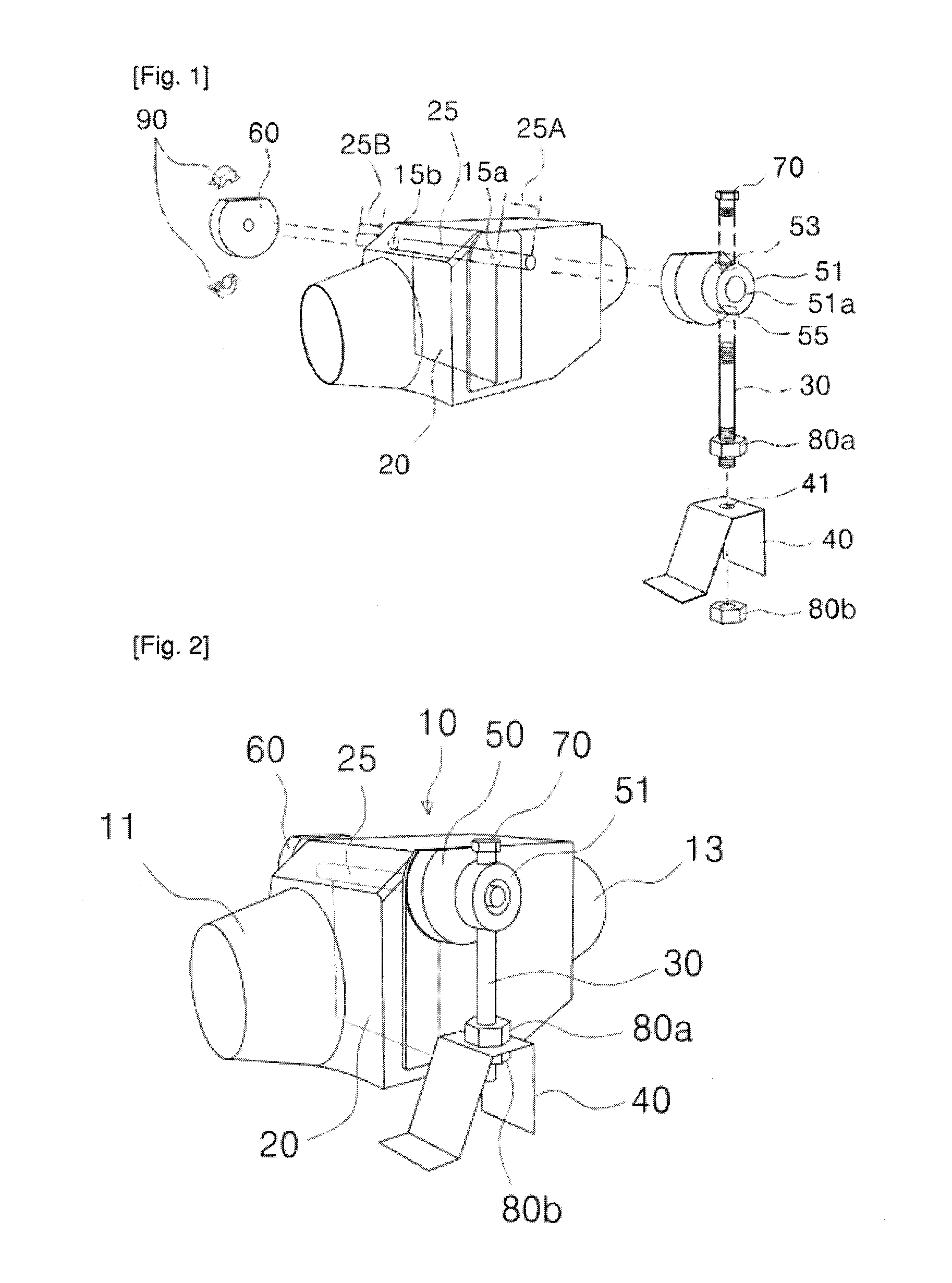
[0023]FIG. 1 is an exploded perspective view showing the structure of an apparatus for automatic control of exhaust pressure of an internal combustion engine according to an embodiment of the present invention, and FIG. 2 is an assembly drawing of FIG. 1.

[0024]With reference to FIGS. 1 and 2, the apparatus for automatic control of exhaust pressure according to an embodiment of the present invention includes: a body 10; a pressure control plate 20; a controlling pendulum 30; and a pendulum blade 40.

[0025]A core concept of the ...


PUM


Abstract

The present invention relates to an apparatus for automatic control of the exhaust pressure of an internal combustion engine. The apparatus includes: a body having an inlet and an outlet for exhaust gas; a pressure control plate, which is a thin plate placed between the inlet and outlet inside the body, designed to rotate along a vertical direction with respect to the ground, within a particular range of angles; a rotational shaft, which is a bar coupled to one side of the pressure control plate that allows it to have a substantial vertical-rotation movement; first and second side elements, attached on both sides of the body's exterior and affixed to the protruding part of the rotational shaft extending outward through the holes on both sides; a controlling pendulum coupled to the first side element for setting the initial gradient of the pressure control plate; and a pendulum blade, coupled to a lower portion of the controlling pendulum, which moves in vertical rotation within a particular range of angles by means of air resistance generated during the operation of a vehicle and which, interlocked with the vertical rotational movement, causes the pressure control plate to move in vertical rotation also.

Description

TECHNICAL FIELD [0001]The present invention relates to an apparatus for automatically controlling the exhaust pressure of an internal combustion engine, more particularly to an apparatus for automatically controlling the exhaust pressure of an internal combustion engine that creates an optimal exhaust pressure environment according to the output of the internal combustion engine by automatically controlling how far the exhaust passage is opened and closed, by way of a pressure control plate configured to rotate within a particular range of angles in correspondence with the speed of the vehicle.BACKGROUND ART [0002]The general four-stroke cycle of an internal combustion engine consists of intake, compression, explosion, and exhaust, in that order. With reference to the stroke continuing from exhaust to intake, the inlet valve opens and the outlet valve closes at the time of intake; however, for a very short time before the outlet valve closes, there exists a valve overlap time duri...

Claims


Application Information

Patent Timeline
Patent Type & Authority Applications(United States)
IPC IPC(8): F01N1/00F01N13/08
CPCF02D9/04F02D9/1065F02D9/103F01N13/08F01N13/00
Inventor JANG, YOUNG GEUN
Owner JANG KEUN JIN
Why Eureka
Try Eureka