
Method of Sealing Annular Space Between Inner and Outer Upright Tubes

a technology of annular space and inner tube, which is applied in the direction of fluid pressure sealing joints, pipe elements, fluid removal, etc., can solve the problems of surface casing failure, contamination of groundwater, and seal may not be able to handle significant pressur

Active Publication Date: 2011-06-02
SPENCE DEAN +2
View PDF12 Cites 4 Cited by
  • Summary
  • Abstract
  • Description
  • Claims
  • Application Information

AI Technical Summary

Benefits of technology

The method may include additional step (c) of covering the annular seal formed in step (b) with a backing member to increase a level of pressure bearable at the seal from below.
The method may comprise installing a locking member over the cover member to help retain the cover member and the annular seal in place under exposure to pressure from below.

Problems solved by technology

Normally the valve is left open so that vent flow gas is released into the atmosphere instead of building up pressure within the well, as sufficient pressure build-up could lead to failure of the surface casing and resulting contamination of groundwater.
However, a potential problem with this solution is that the resulting seal may not be able to handle significant pressures that may be experienced during shut-in testing for surface casing vent flow.

Method used


Image

  • Method of Sealing Annular Space Between Inner and Outer Upright Tubes
  • Method of Sealing Annular Space Between Inner and Outer Upright Tubes
  • Method of Sealing Annular Space Between Inner and Outer Upright Tubes

Examples


Embodiment Construction

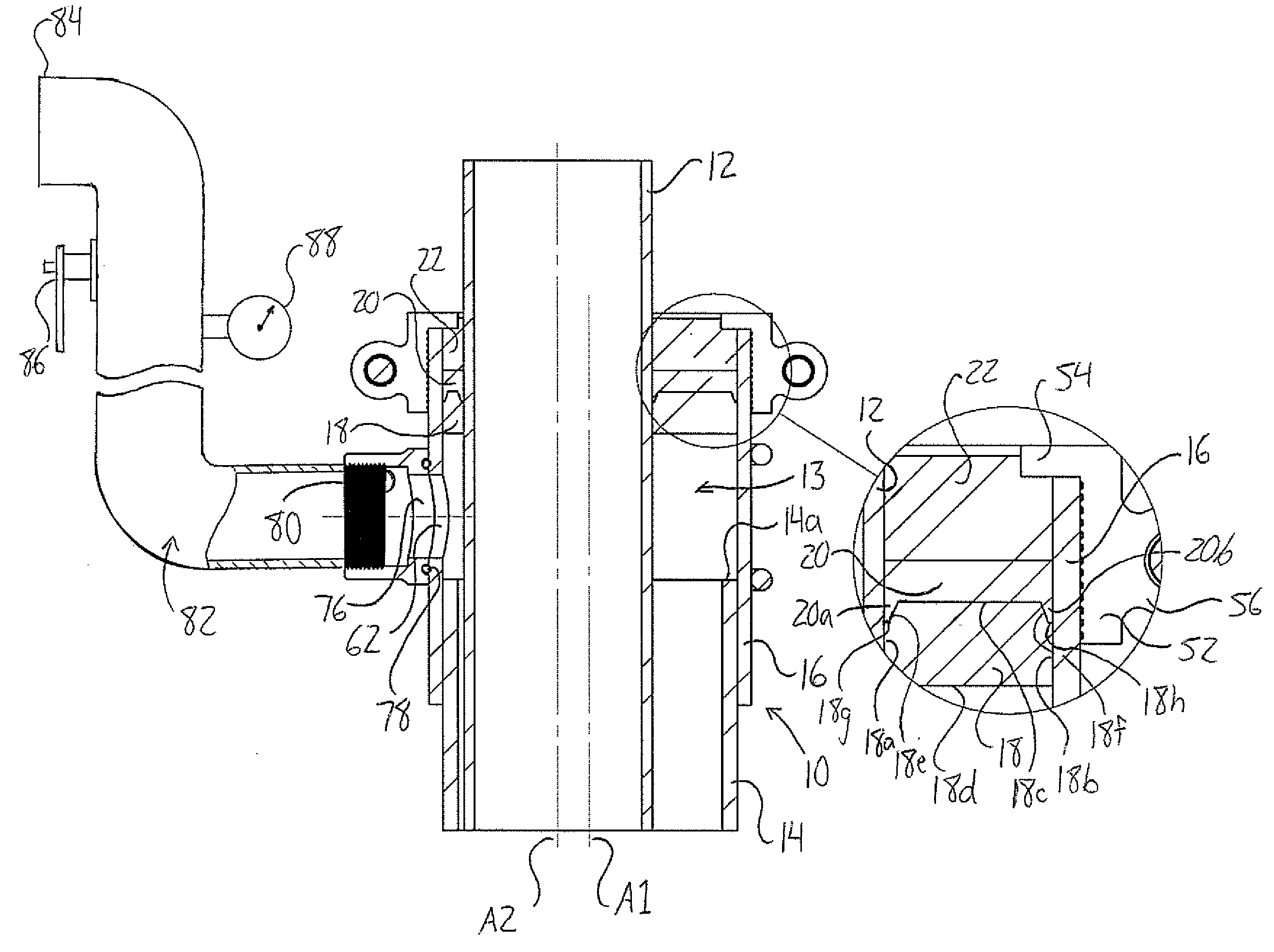
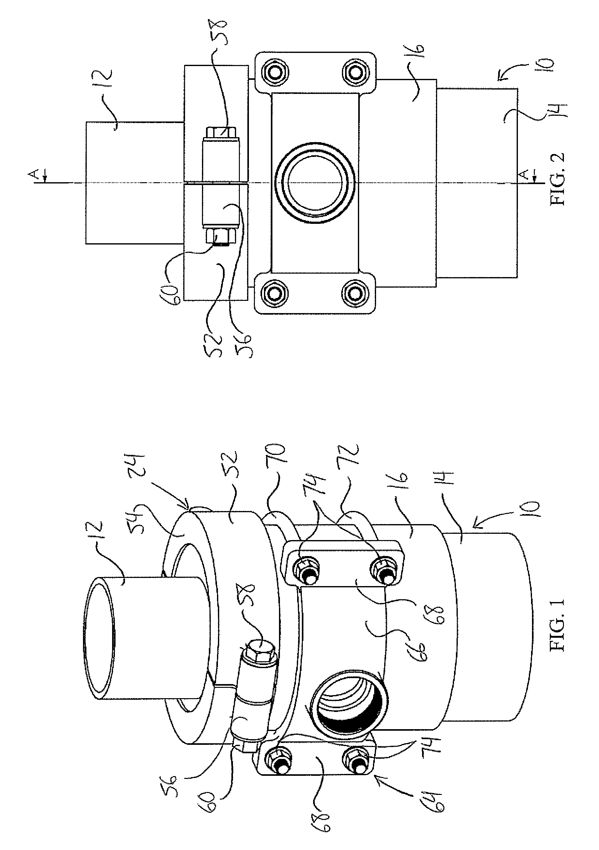
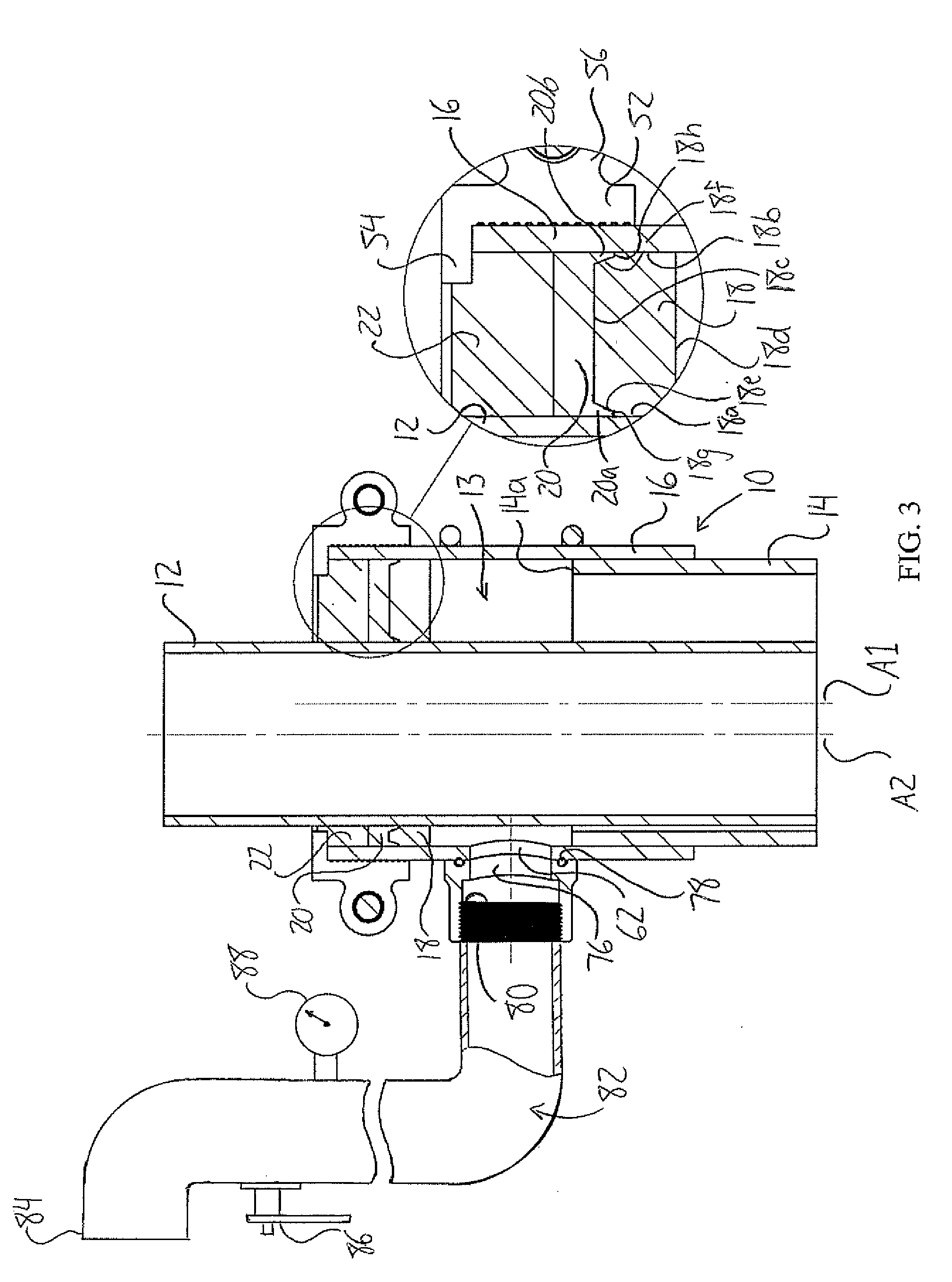
FIGS. 1 to 3 illustrate a completed installation of a seal between a surface casing installation 10 and production casing installation 12 at a well head of a gas well in accordance with a method of the present invention. In a conventional manner, the production casing installation 12 passes vertically downward through the vertically oriented surface casing installation 10 that depends downward from ground level at an upper end of the well. In the figures, only a partial portion of the surface casing installation 10 is shown, specifically an upper end of an uppermost surface casing section 14 externally threaded at both ends and an internally threaded casing collar 16 fastened to this upper end 14a of the surface casing section 14 by engagement of the mating threads. The resulting structure is that the surface casing collar 16 closes coaxially around and projects upward from the top end of the uppermost surface casing section 14 and the production casing 12 passes vertically through ...


PUM


Abstract

A method of sealing annular space between an upright outer tube and an upright inner tube extending within the outer tube along an axial direction thereof involves pouring a liquid seal material into the annular space onto a support member fitted within the annular space between the outer tube and the inner tube in a manner substantially closing around the inner tube. The liquid seal material is poured in an amount sufficient to fill radial space between the inner tube and the outer tube fully around the inner tube, the liquid seal material is then cured to form an annular seal between the inner tube and the outer tube. The method is useful in sealing of the annular spacing between the surface and production casing of a gas well and installing a venting system to facilitate controlled venting of the annular space.

Description

FIELD OF THE INVENTIONThe invention relates generally to a method of sealing annular space between an upright outer tube and an upright inner tube extending within the outer tube along an axial direction thereof, and more particularly to sealing such annular space between the surface and production casing of a gas producing well.BACKGROUND OF THE INVENTIONWith rising environmental concerns, more attention than ever is being paid to the issue of surface casing vent flow in gas producing wells.In a natural gas well, the subterranean gas is to be produced by flowing upward to the surface through the production casing of the well. Surface casing vent flow refers to movement of gas upward around the outside of the production casing and discharging into the atmosphere around the wellhead through an annular space between the production casing and the larger diameter surface casing that closes around the production casing from the ground surface downward over an upper portion of the product...

Claims


Application Information

Patent Timeline
IPC IPC(8): E21B33/04F16J15/10F16J15/14
CPCE21B33/02F16L39/005F16J15/14E21B33/04
Inventor SPENCE, DEANBLOMGREN, GORDRISKE, RANDY
Owner SPENCE DEAN
Learn More