Voltage booster apparatus for power steering system

a technology of voltage booster and power steering system, which is applied in the direction of motor/generator/converter stopper, electronic commutation motor control, dynamo-electric converter control, etc., can solve the problem of not being able to interrupt the power supply to the booster circuit too frequently, and affecting the safety of the system

Active Publication Date: 2011-06-02
DENSO CORP
View PDF28 Cites 23 Cited by
  • Summary
  • Abstract
  • Description
  • Claims
  • Application Information

AI Technical Summary

Benefits of technology

[0016]It is therefore an object of the present invention to provide a voltage booster apparatus for a power steering system, which safely returns the system to a regular operation by confirming no short-circuit failure of a subject element even when a power supply relay is turned off erroneously.

Problems solved by technology

In some cases, the switching elements provided in the voltage booster circuit are subjected to a short-circuit failure.
As the fail-safe operation time is set shorter, detection error may arise more often.
This determination error sometimes arises, when a power supply terminal for the booster circuit only momentarily cannot keep contact due to vibration or the like.
It is not desirable to interrupt the power supply to the booster circuit too frequently by such a momentary disconnection.

Method used


Image

  • Voltage booster apparatus for power steering system
  • Voltage booster apparatus for power steering system
  • Voltage booster apparatus for power steering system

Examples


first embodiment

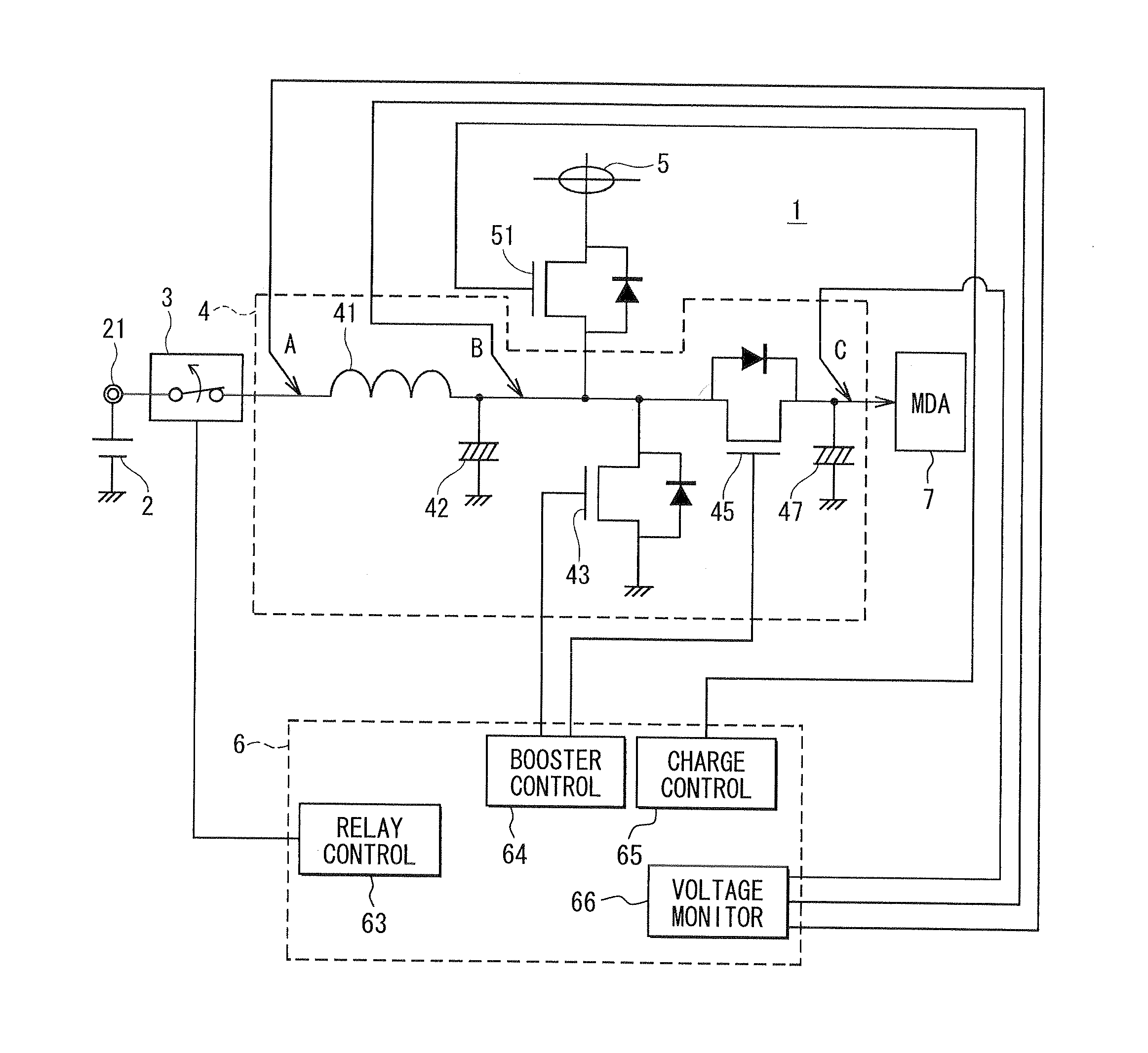
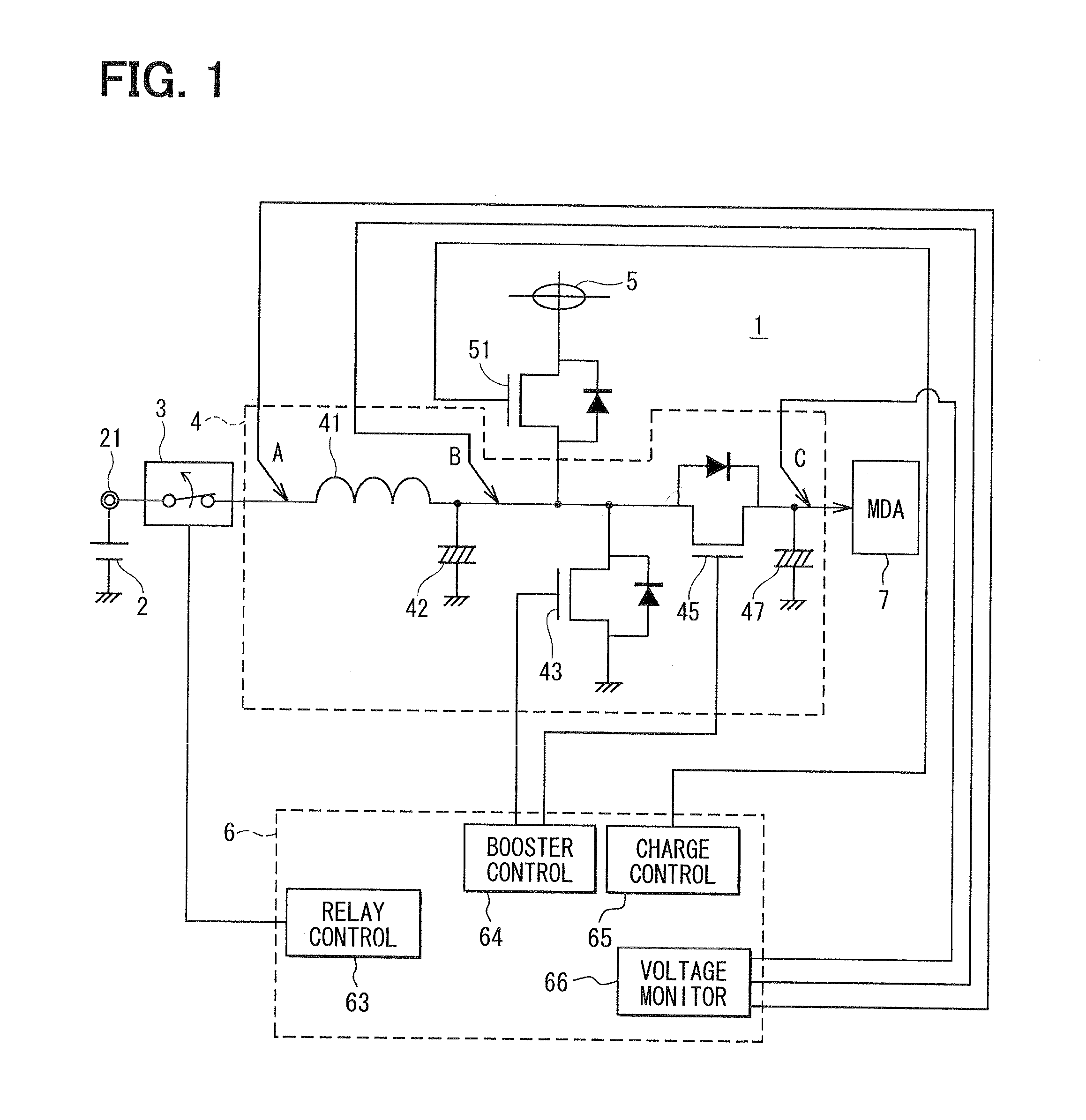
[0025]Referring to FIG. 1, a power steering system is configured to generate a torque by an electric motor for power-assisting a steering operation of a steering wheel based on a steering torque signal and a vehicle travel speed signal. The motor is, for example, a three-phase brushless motor (not shown). A voltage booster apparatus 1 is provided to control the motor by a motor drive apparatus (MDA) 7.

[0026]The voltage booster apparatus 1 includes a voltage booster circuit 4, which is configured to boost a battery voltage VI supplied by a battery 2 and supply the motor drive apparatus 7 with a boosted voltage Vc as a booster output voltage. The voltage booster circuit 4 includes a coil 41, two capacitors 42, 47 and two switching elements, which are a step-up FET 43 and a step-down FET 45.

[0027]The battery 2 is mounted on the vehicle and its negative terminal is ground. A power supply terminal 21 of the battery 2 is provided between the battery 2 and a power supply relay 3 for supply...

second embodiment

[0058]According to a second embodiment, the operation restoration processing of the first embodiment shown in FIG. 3 is modified as shown in FIG. 4.

[0059]Specifically, S11 to S14 are executed in the same manner as in the first embodiment. At S17B, however, the step-up FET 43 is turned on by the booster circuit control section 64 with the power supply relay 3 being maintained in the OFF state. The charge stored in the coil output capacitor 42 is discharged to the ground from the circuit point B through the step-up FET 43. As a result, the coil output voltage VB falls. If the step-down FET 45 is normal and not short-circuited, the boosted voltage VC at the circuit point C is maintained. If the step-down FET 45 is short-circuited, on the other hand, a current flows in reverse from the circuit point C to the circuit point B. As a result, the boosted voltage VC falls to be about the coil output voltage VB.

[0060]It is checked at S18B whether the boosted voltage VC is far higher than the c...

third embodiment

[0062]According to a third embodiment, the operation restoration processing of the second embodiment shown in FIG. 4 is modified as shown in FIG. 5. Specifically, S18B in the second embodiment is replaced with S18C in the third embodiment.

[0063]As described in the second embodiment, if the step-down FET 45 has the short-circuit failure, the boosted voltage VC falls to as low as the coil output voltage VB due to the current flow in reverse from the circuit point C to the circuit point B. It is checked at S18C whether the boosted voltage VC falls rapidly or slowly based on the monitored voltage acquired by the voltage monitor section 66. If the check result at S18C is YES, that is, a fall speed is less than a predetermined speed, S19 is executed. If the check result at S18 is NO, that is, a fall speed is greater than the predetermined speed, it is determined that the step-down FET 45 is short-circuited. In this case, at S20, the power supply relay 3 is maintained in the OFF state so t...


PUM


Abstract

In a voltage booster apparatus, a charge control transistor is turned on to charge a coil output capacitor and a booster output capacitor and then turned off, thereby confirming rise of a coil output voltage and a booster output voltage. A power supply relay is turned on to restore a booster operation thereby to check rise of the booster output voltage. If both of a step-up FET and a step-down FET are not in short-circuit failure, ON state of the power supply relay is fixed thereby to restore a power steering system operation.

Description

CROSS REFERENCE TO RELATED APPLICATION[0001]This application is based on and incorporates herein by reference Japanese Patent Application No. 2009-270374 filed on Nov. 27, 2009.FIELD OF THE INVENTION[0002]The present invention relates to a voltage booster apparatus for a power steering system, which power assists steering of a steering wheel.BACKGROUND OF THE INVENTION[0003]As disclosed in the following patent documents 1, 2 and 3, electric power steering systems are provided conventionally as steering systems in vehicles.[0004]Patent document 1: JP 2003-267247A (JP 3885621)[0005]Patent document 2: JP 2003-319699A[0006]Patent document 3: JP 2009-40149A[0007]According to such conventional electric power steering systems, a voltage booster circuit is provided to boost (step up) a voltage of a battery and supply a motor drive apparatus with a boosted voltage. In the patent documents 2 and 3, the booster circuit is configured with a coil, switching elements, a backflow prevention elemen...

Claims


Application Information

Patent Timeline
Patent Type & Authority Applications(United States)
IPC IPC(8): H02P27/00
CPCH02M3/158
Inventor OGASAWARA, TERUMOTO
Owner DENSO CORP
Why Eureka
Try Eureka