Dielectric resonator in RF filter and assembley method therefor

a dielectric resonator and rf filter technology, applied in the direction of resonators, electrical equipment, antennas, etc., can solve the problems of limiting the use of te01-mode resonator filters, requiring a few times higher fabrication cost and a huge volume, and not being suitable for ultra radio frequency generation, etc., to achieve high efficiency, low cost, and stable temperature characteristics

Active Publication Date: 2011-06-02
KMW INC
View PDF4 Cites 27 Cited by
  • Summary
  • Abstract
  • Description
  • Claims
  • Application Information

AI Technical Summary

Benefits of technology

[0013]As is apparent from the above description, a DR for an RF filter according to the present invention has stable temperature characteristics, compared to a conventional TM-mode resonator. The DR is robust against an external impact and thus its characteristics are maximized with low cost.
[0014]In th

Problems solved by technology

A typical coil-condenser resonant circuit is not suitable for generating an ultra radio frequency due to a large radiation loss.
Although a TE01δ-mode resonator filter has a three times higher Q value than the TEM-mode resonator filter, it requires a few times higher fabrication cost and a huge volume.
That's why the use of the TE01δ-mode resonator filter was restrictive to a Base Station (BS) high-power filter.
Thus, the TE01δ-mode resonator filter is not feasible for small-size products.
If the assembly is not done reliable, the characteristics of the TM-mode resonator are greatly changed with temperat

Method used


Image

  • Dielectric resonator in RF filter and assembley method therefor
  • Dielectric resonator in RF filter and assembley method therefor
  • Dielectric resonator in RF filter and assembley method therefor

Examples


Embodiment Construction

[0023]The matters defined in the description such as a detailed construction and elements are provided to assist in a comprehensive understanding of exemplary embodiments of the invention. Accordingly, those of ordinary skill in the art will recognize that various changes and modifications of the embodiments described herein can be made without departing from the scope and spirit of the invention. Also, descriptions of well-known functions and constructions are omitted for clarity and conciseness.

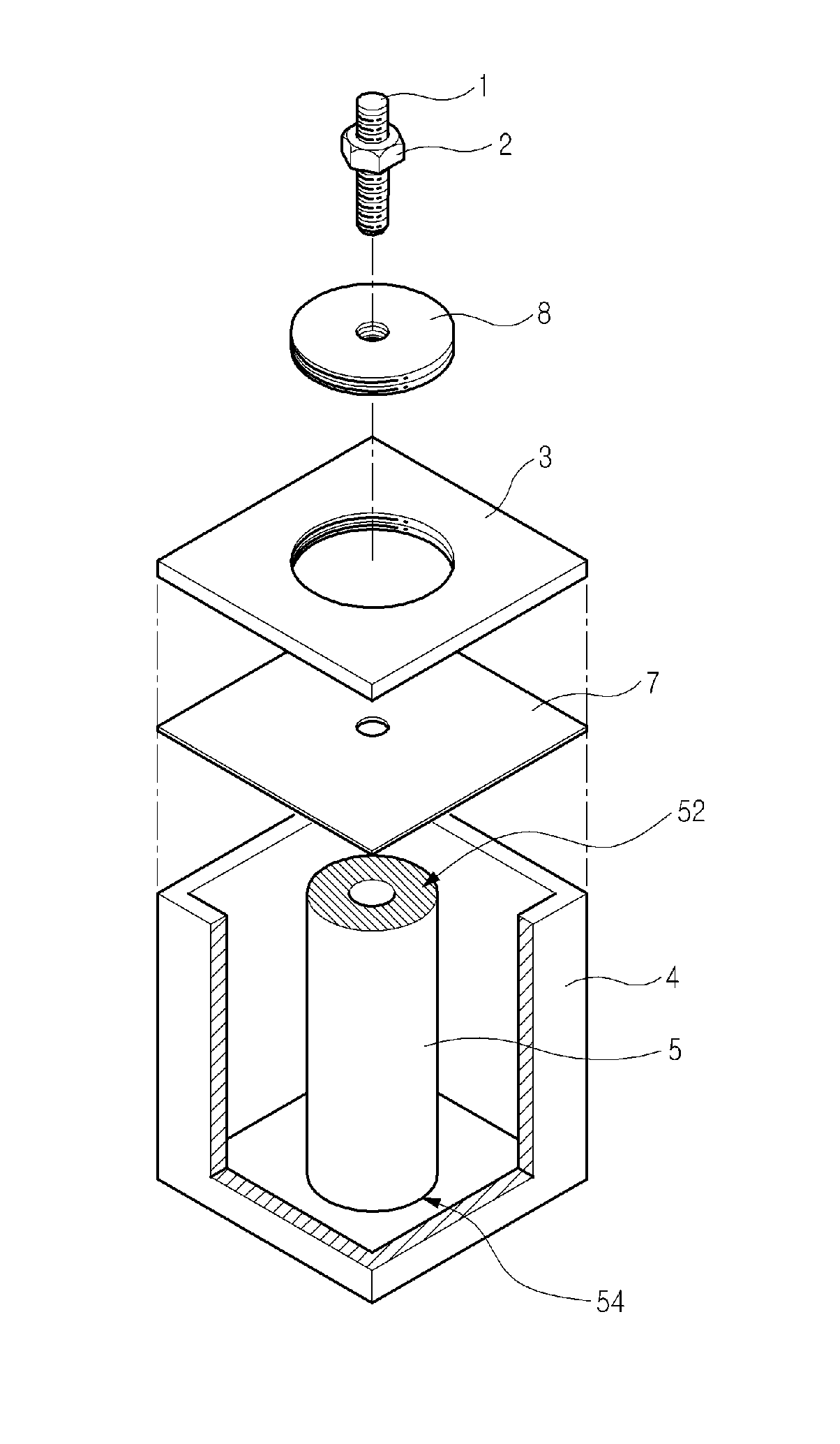
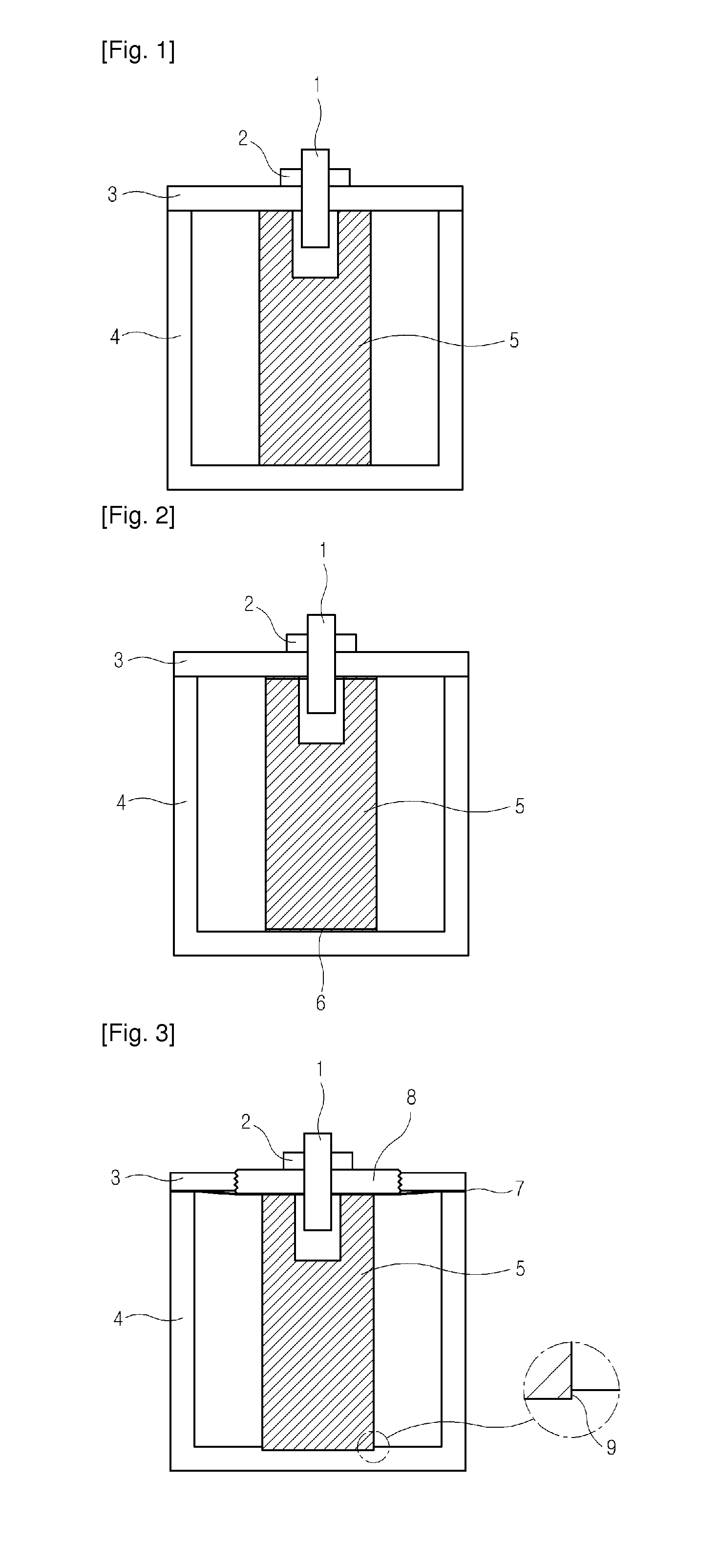
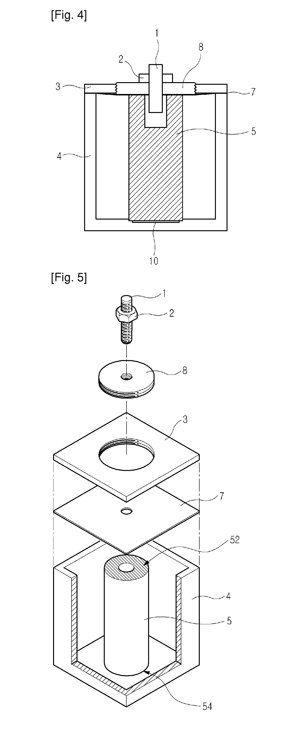
[0024]FIG. 3 illustrates the structure of a TM-mode resonator according to an exemplary embodiment of the present invention, FIG. 4 illustrates an exemplary modification of the TM-mode resonator illustrated in FIG. 3, and FIG. 5 is an exploded perspective view of the TM-mode resonator illustrated in FIG. 3.

[0025]Referring to FIGS. 3, 4 and 5, the TM-mode resonator according to the present invention has the dielectric resonance element 5 in the shape of a rod at the center of the housing spa...


PUM

PropertyMeasurementUnit
Temperatureaaaaaaaaaa
Dielectric polarization enthalpyaaaaaaaaaa
Frequencyaaaaaaaaaa

Abstract

A dielectric resonator in a radio frequency filter is provided, in which a dielectric resonance element is fixed at the center of a housing space formed by a cover and a housing, a guide groove is formed into a bottom of the housing, for allowing the dielectric resonance element to be inserted therein, a metal plate is interposed between the cover and the housing, and a dielectric fixing screw is engaged with the cover at a position corresponding to an upper end portion of the dielectric resonance element by screwing, for fixing the dielectric resonance element by pressing the upper end portion of the dielectric resonance element.

Description

TECHNICAL FIELD[0001]The present invention generally relates to a Radio Frequency (RF) filter. More particularly, the present invention relates to a dielectric resonator in an RF filter.BACKGROUND ART[0002]An RF filter (e.g. a Dielectric Resonator (DR) filter, a cavity filter, a waveguide filter, etc.) has a kind of circuit cylinder structure for resonating at a radio frequency or ultra radio frequency. A typical coil-condenser resonant circuit is not suitable for generating an ultra radio frequency due to a large radiation loss. The RF filter has a plurality of resonators each forming a metal cylindrical or rectangular cavity coated with a conductive material and a dielectric resonance element or a resonance element configured to be a metal resonance rod is provided in the cavity. The resulting existence of an electro-magnetic field only at a unique frequency makes ultra radio frequency resonance possible.[0003]RF filters may be categorized into Transverse Magnetic (TM) mode, Trans...

Claims


Application Information

Patent Timeline
IPC IPC(8): H01P7/10H05K13/00
CPCY10T29/49016H01P7/10H01P1/20
Inventor PARK, NAM-SHINKIM, SUNG-KYUNKWON, JUNG-HYUN
Owner KMW INC
Why Eureka
Try Eureka