Absorptive device to carbon dioxide in the air

Inactive Publication Date: 2011-06-09
MING YANG HSIEN +1
View PDF10 Cites 37 Cited by
  • Summary
  • Abstract
  • Description
  • Claims
  • Application Information

AI Technical Summary

Benefits of technology

[0019]The object of the present invention is to provide an absorptive device to carbon dioxide in the air, which can preferably increases an absorptive efficiency thereof.
[0026]Thus, since the present invention utilizes the rotating packed bed to carry on the chemical absorption, the related equipment could be minified, and lower energy consumption for transporting the filled absorbent to the top of the conventional packed column could be achieved. By means of the energy reduction of the rotating packed bed, a more competitive application in the market can be accomplished to greatly decrease the cost. Thus, in economic terms, the present invention would be a carbon dioxide eliminating device with high efficiency.

Problems solved by technology

The gas of greenhouse has resulted in a serious global warming problem.
Since most absorbent belong to alkaline solution, the absorbent column, the reviving column, and other pipes would be facilely corroded.
The involved parameters are so variable that the operation thereof is accordingly complicated.
However, the cost would be accordingly increased, which is in inconformity with economic benefits as well as unfavorable to the competitiveness in the market.
However, an inner and an outer circumfluent passages of this countercurrent rotating packed bed have a great differential in the sectional areas, so the gas speed would vary prodigiously.
As a result, a resistance to the gas would be increased, and this means is accordingly improper to be applied to the gas-liquid mass transfer of a high gas flow, such as absorption.

Method used


Image

  • Absorptive device to carbon dioxide in the air
  • Absorptive device to carbon dioxide in the air
  • Absorptive device to carbon dioxide in the air

Examples


Embodiment Construction

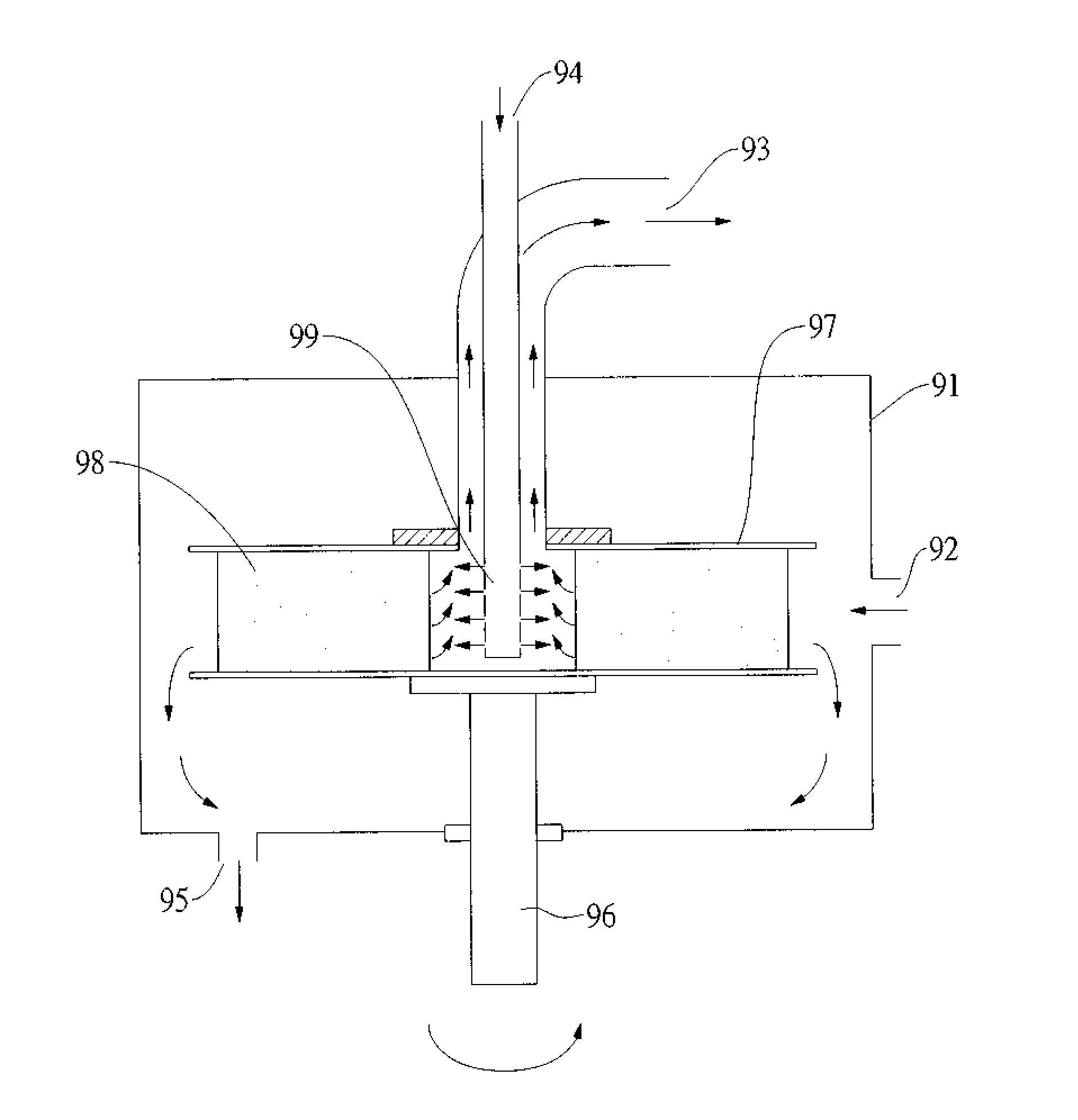
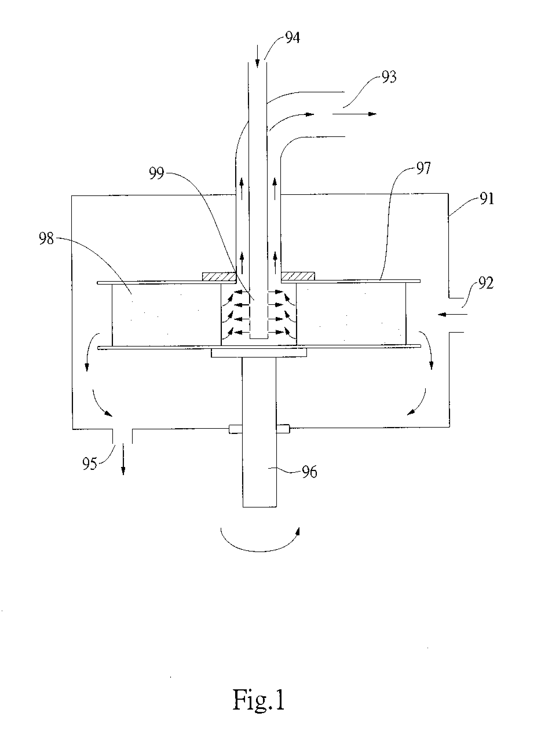
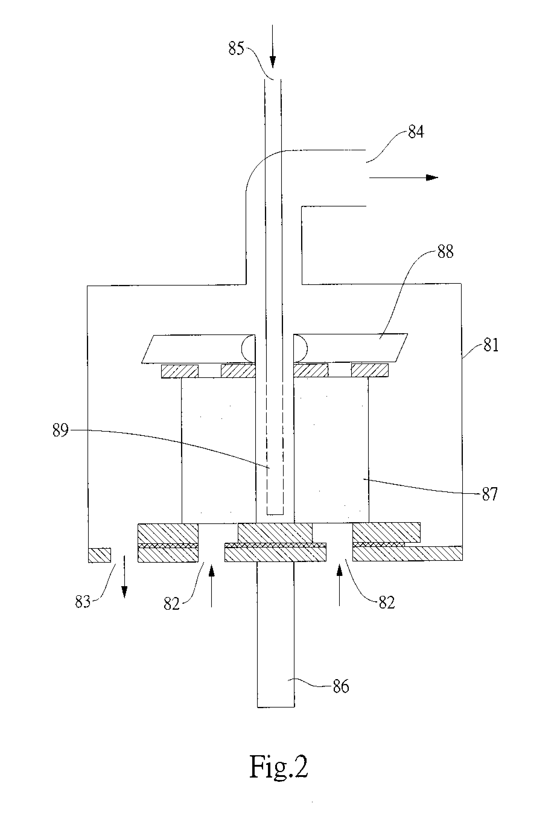
[0031]Referring to FIG. 3, the present invention essentially comprises a rotating packed bed 1, an air pump 2, an absorbent reservoir 3, and a water pump 4.

[0032]Wherein, the rotating packed bed 1 includes a sealed housing 11 that disposes an air entrance 12 and an absorbent exit 13 thereon. Moreover, an air exit 14 and an absorbent entrance 15 are disposed on a top center of the housing. A motor 16 with a filler 17 of a high rotational speed is disposed inside the housing, and a liquid distributor 18 is disposed at a center of the filler 17 for being in communication with the absorbent entrance.

[0033]Further, an air pump 2 impels air from the air entrance 12 into the housing 11, an absorbent reservoir 3 saves an absorbent extruded from the absorbent exit 13, and a water pump 4 impels the absorbent in the absorbent reservoir 3 from the absorbent entrance 15 into the housing 11.

[0034]In operation, the absorbent passes from the absorbent entrance 15 through the liquid distributor 18 a...


PUM

PropertyMeasurementUnit
Magnetic fieldaaaaaaaaaa
Lengthaaaaaaaaaa
Lengthaaaaaaaaaa

Abstract

An absorptive device to carbon dioxide comprising a rotating packed bed includes a sealed housing, in which a filler is speedily rotated by a motor. A liquid distributor on the filler center communicates an absorbent entrance. An air pump impels the air into the housing; an absorbent reservoir saves an absorbent extruded from an absorbent exit; a water pump forces the absorbent within the absorbent reservoir into the housing. The absorbent flows through the liquid distributor into the filler center; the air enters the center through the filler. The absorbent spurts via the centrifugal force created by the super gravity field at a speedy rotation more than 100 G to meet the carbon dioxide in the air at the filler center, thence achieving a chemical absorption to absorb carbon dioxide, discharging redundant air from the air exit, and recycling the absorbent with the absorption of carbon dioxide in the absorbent reservoir.

Description

BACKGROUND OF THE INVENTION[0001]1. Field of the Invention[0002]The present invention relates to an absorptive device to carbon dioxide in the air, more particularly to a device that substitutes a novel rotating packed bed for the conventional packed column so as to recycle the carbon dioxide with a chemical absorption process.[0003]2. Description of the Related Art[0004]The gas of greenhouse has resulted in a serious global warming problem. Wherein, in the greenhouse gas, carbon dioxide (CO2) is in the largest proportion of about 55%. Thus, to decrease and control the amount of the greenhouse gas as well as to develop the processing techniques thereof is definitely a tendency in the world. Accordingly, the present invention would focus on how to efficiently absorb the carbon dioxide in the air.[0005]A chemical absorption process is presently applied to recycle the carbon dioxide. Wherein, the process utilizes an absorbent reacting on the carbon dioxide to cause a chemical reaction ...

Claims


Application Information

Patent Timeline
IPC IPC(8): B01D53/14
CPCB01D53/1475B01D53/18B01D53/62B01D2251/2062Y02C10/06B01D2251/604B01D2257/504Y02C10/04B01D2251/30Y02A50/20Y02C20/40
Inventor MING, YANG HSIENWEN, CHEN YONG
Owner MING YANG HSIEN
Why Eureka
Try Eureka