Feedwell dilution system for thickeners in oil sands

a technology of dilution system and thickener, which is applied in the direction of liquid displacement, multi-stage water/sewage treatment, separation process, etc., can solve the problems of stray bitumen accumulation, added pump and power cost, and lack of practical means to adjust the dilution ratio, so as to facilitate the formation of clarified liquid

Active Publication Date: 2011-06-09
F L SMIDTH & CO AS
View PDF19 Cites 7 Cited by
  • Summary
  • Abstract
  • Description
  • Claims
  • Application Information

AI Technical Summary

Benefits of technology

[0011]In accordance with another exemplary embodiment, a system for diluting an influent feed stream entering into a settling tank, comprises: a settling tank, which is structured to provide settling of particulate material residing within an influent feed stream and facilitate the formation of a clarified liquid in an upper region thereof; a feedwell disposed in the settling tank, the feedwell having an outer wall defining an outer perimeter of the feedwell; and a pair of eductor assemblies, each of the eductor assemblies comprising: a feed pipe which converges to a narrow throat portion or nozzle; a mix tube positioned downstream from the narrow throat portion that is sized and configured to provide mixing of the influent feed stream and the clarified liquid drawn from the settling tank; and an enclosure, which is installed around the narrow throat portion of the feed pipe and an inlet portion of the mix tube and includes an open-ended portion on a bottom thereof, which is sized and configured to allow the clarified liquid to be pulled into the mix tube from below the inlet portion of the mix tube.

Problems solved by technology

Problems with using a pump include the added expense and maintenance of the pump and power costs for operation thereof.
The main drawback of the spill method is the lack of practical means to adjust the dilution ratio.
It can be appreciated that the operation of a feedwell dilution system for thickeners in oil sands (or tar sands) can also present additional problems including accumulation of stray bitumen within the feedwell dilution system, including the feedwell (or feedwell assembly).
However, the operation of a feedwell dilution system in oil sands thickening applications, including tailings, can experience stray, or residual, bitumen from the extraction process, which accumulates on the surface of the thickener and can foul the dilution system and feedwell, thus lowering the dilution efficiency and flocculation of the oil sands slurry feeding the thickener.

Method used


Image

  • Feedwell dilution system for thickeners in oil sands
  • Feedwell dilution system for thickeners in oil sands
  • Feedwell dilution system for thickeners in oil sands

Examples


Embodiment Construction

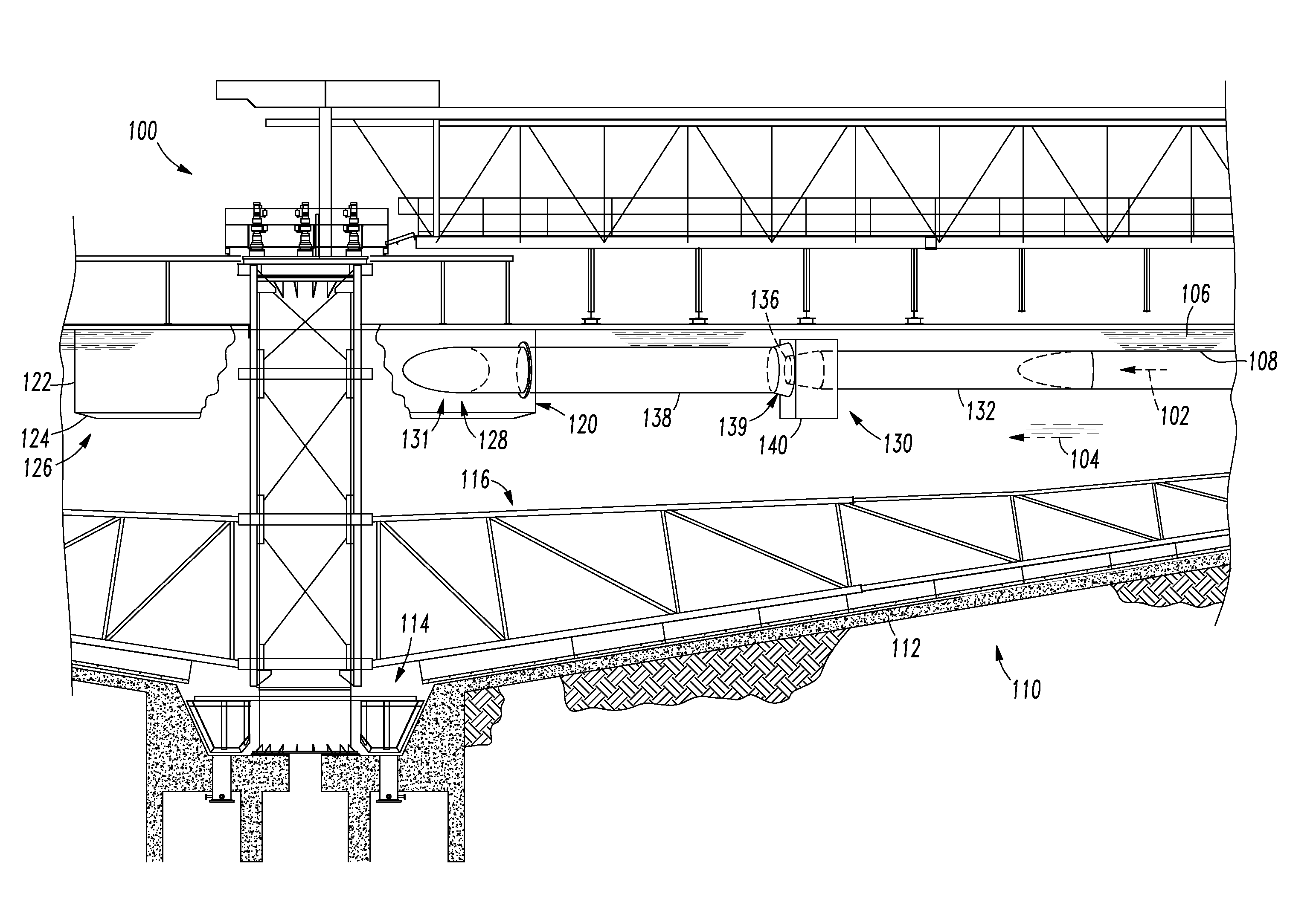
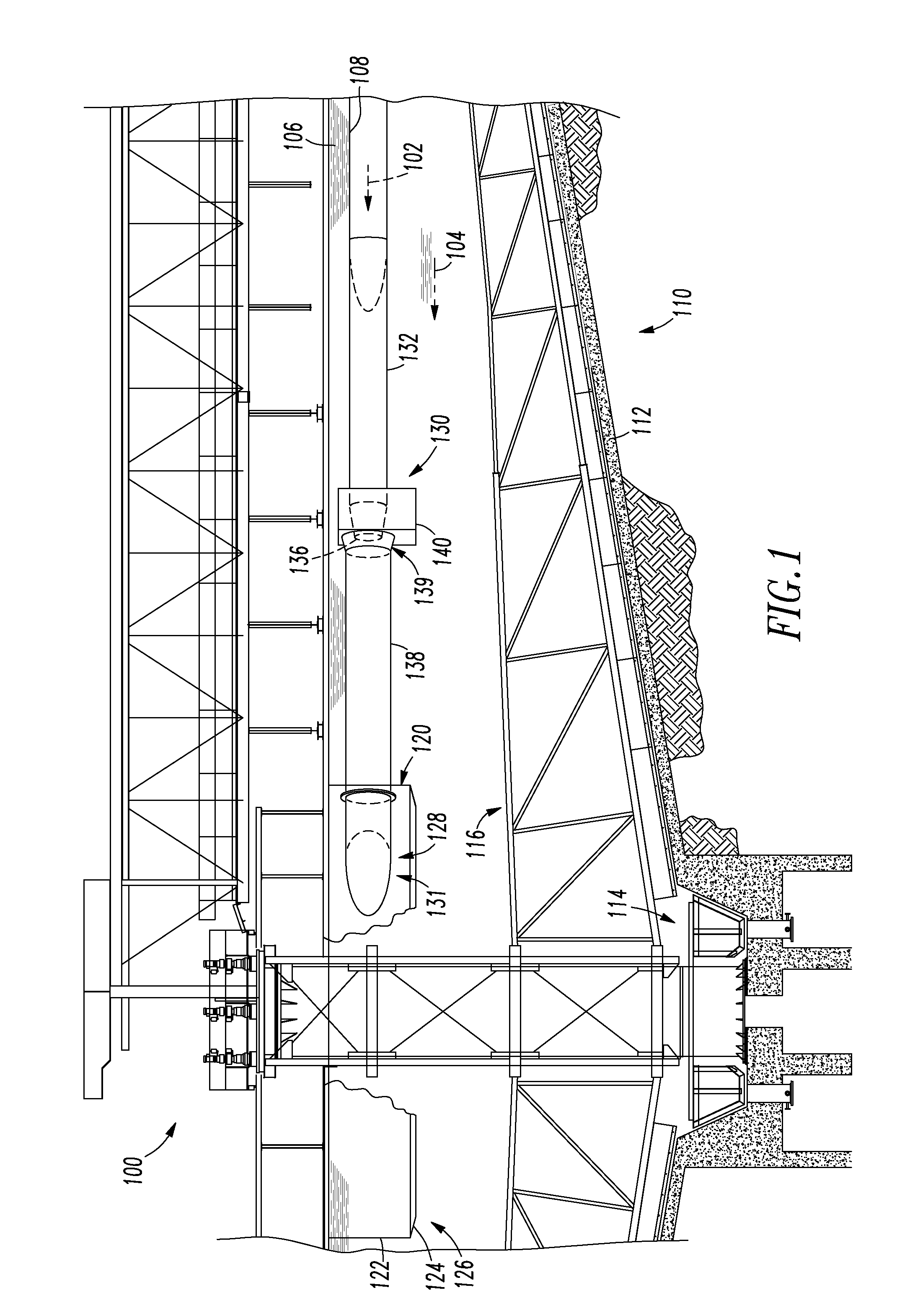
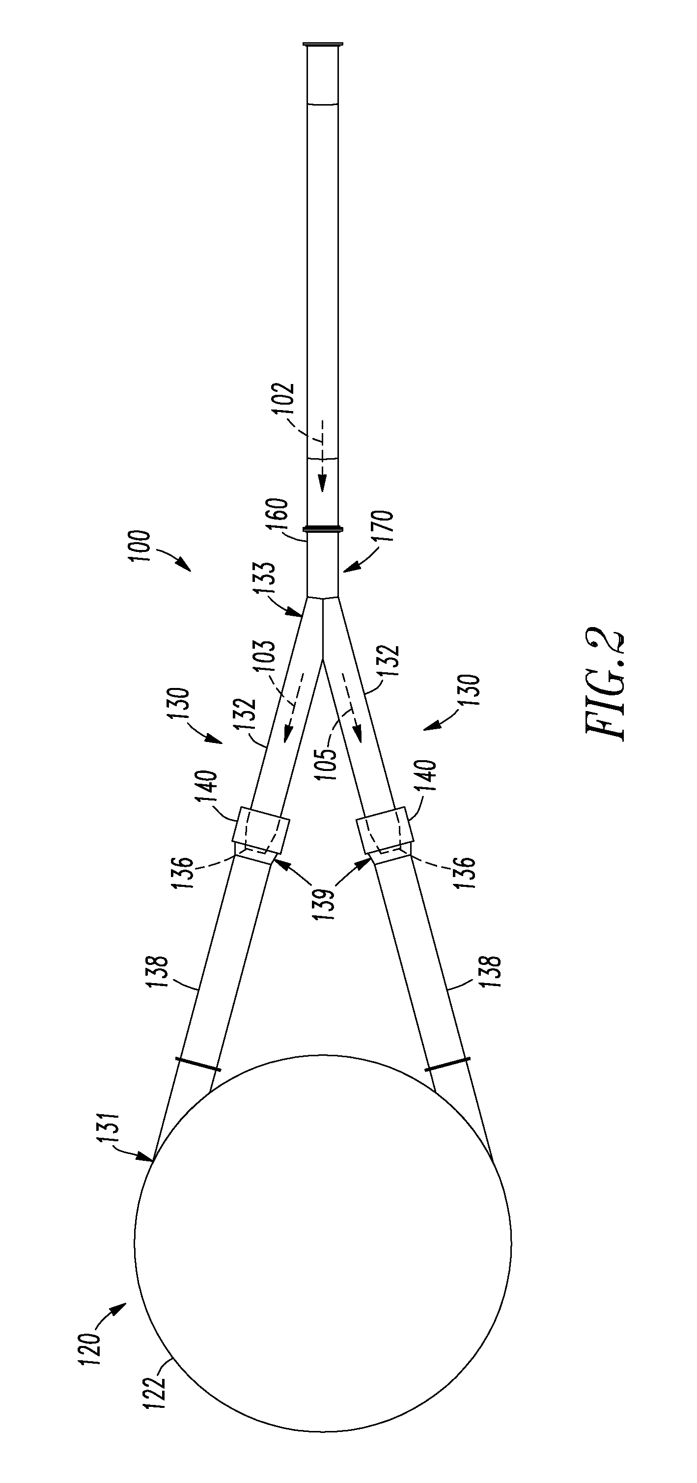
[0022]FIG. 1 is a side elevation view of a feedwell dilution system 100 for thickeners applied in oil sands in accordance with an exemplary embodiment. As shown in FIG. 1, the feedwell dilution system 100 for diluting an influent feed stream 102 comprises a settling tank 110, at least one eductor assembly 130, which delivers the influent stream 102 and diluent (i.e., dilution water, clarified liquid and / or clarified liquor) 104 to a feedwell or feedwell assembly 120.

[0023]As shown in FIG. 1, the settling tank 110 preferably includes a floor 112 and a continuous wall (not shown), which defines a volume within which the clarification process takes place. The tank 110 also includes an underflow outlet 114 for removing settled solids from the tank 110 and a fluid discharge outlet for directing clarified liquid 104 away from the tank 110. In accordance with an exemplary embodiment, the tank 110 includes a rake assembly 116 having rake arms for sweeping along the floor of the tank 110, an...


PUM

PropertyMeasurementUnit
momentumaaaaaaaaaa
areaaaaaaaaaaa
distanceaaaaaaaaaa

Abstract

A feedwell dilution system for diluting an influent feed stream, which include at least one eductor assembly, and a feedwell assembly. The at least one eductor assembly includes a feed pipe which converges to a narrow throat portion or nozzle; a mix tube positioned downstream from the narrow throat portion that is sized and configured to provide mixing of the influent feed stream and a clarified liquid drawn from a settling tank; and an enclosure, which is installed around the narrow throat portion and an inlet portion of the mix tube and includes an open-ended portion on a bottom thereof, which is sized and configured to allow a clarified liquid to be pulled into the mix tube from below the inlet portion of the mix tube. The feedwell assembly is sized and configured to receive the mixture of the influent feed stream and the clarified liquid from the mix tube.

Description

FIELD OF THE INVENTION[0001]This application relates generally to feedwells for diluting and dispensing an influent slurry feed stream into a settling tank or basin, and more specifically to a self-diluting feedwell for diluting and dispensing an influent slurry feed stream into a thickener, clarifier, or settling tank without the need for a dilution pump or additional dilution material from an outside source, and which operates in the oil sands extraction and recovery process, including tailings treatment, and prevents stray bitumen from fouling the dilution system and feedwell.BACKGROUND OF THE INVENTION[0002]Slurries or suspensions comprising liquids carrying suspended particles are typically subjected to a process called clarification to separate suspended particles from supernatant liquid. Typically, clarification is accomplished by continuously feeding an influent slurry or suspension feed stream into a settling tank or thickener, where suspended particles are allowed to gravi...

Claims


Application Information

Patent Timeline
Patent Type & Authority Applications(United States)
IPC IPC(8): B01D21/24B01D21/01
CPCB01D21/0021B01D2221/04B01D21/2427B01D21/2411
Inventor LAROS, TIMOTHY J.BACZEK, FRANK ANDREW
Owner F L SMIDTH & CO AS
Why Eureka
Try Eureka