
Apparatus and method for evaluating capacitor

a technology of large capacity capacitor and apparatus, which is applied in the direction of capacitor testing, capacitor manufacture, instruments, etc., can solve the problems of long measurement evaluation time, large capacity capacitor cannot be evaluated by the method of measuring small capacity capacitor according to prior, and achieve the effect of rapid measuremen

Inactive Publication Date: 2011-06-09
SAMSUNG ELECTRO MECHANICS CO LTD
View PDF0 Cites 25 Cited by
  • Summary
  • Abstract
  • Description
  • Claims
  • Application Information

AI Technical Summary

Benefits of technology

[0011]An aspect of the present invention provides an apparatus and a method for evaluating a capacitor that can automatically measure the ESR, capacitance, and self discharge resistance of the capacitor and rapidly perform the measurement.

Problems solved by technology

However, since the large capacity capacitor outputs current from several amperes to several hundred amperes, it cannot ignore voltage drop by equivalent series resistance, such that the large capacity capacitor cannot be evaluated by the method for measuring the small capacity capacitor according to prior art.
Further, it takes a long time (for example, 2-4 hours) for the large capacity capacitance to be charged once or to discharge charged voltage, such that the measurement evaluation time for judging pass / fail of a large capacity capacitor is inevitably increased as compared to that of the small capacity capacitor as the capacity of capacitors is increased.
As described above, it takes an excessive amount of time to measure the large capacity capacitor, which becomes an obstacle in the mass production thereof.

Method used


Image

  • Apparatus and method for evaluating capacitor
  • Apparatus and method for evaluating capacitor
  • Apparatus and method for evaluating capacitor

Examples


Embodiment Construction

[0036]Exemplary embodiments of the present invention will now be described in detail with reference to the accompanying drawings.

[0037]The present invention should not be construed as being limited to the embodiments set forth herein and the embodiments may be used to help understanding of the technical idea of the present invention. Like reference numerals designate like components having substantially the same constitutions and functions throughout the drawings of the present invention.

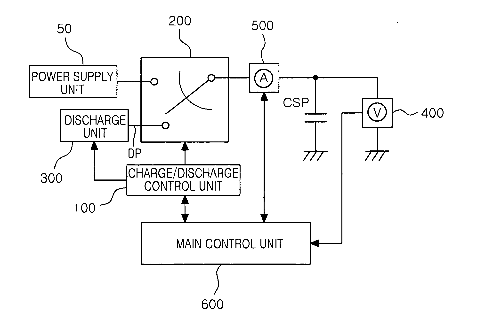
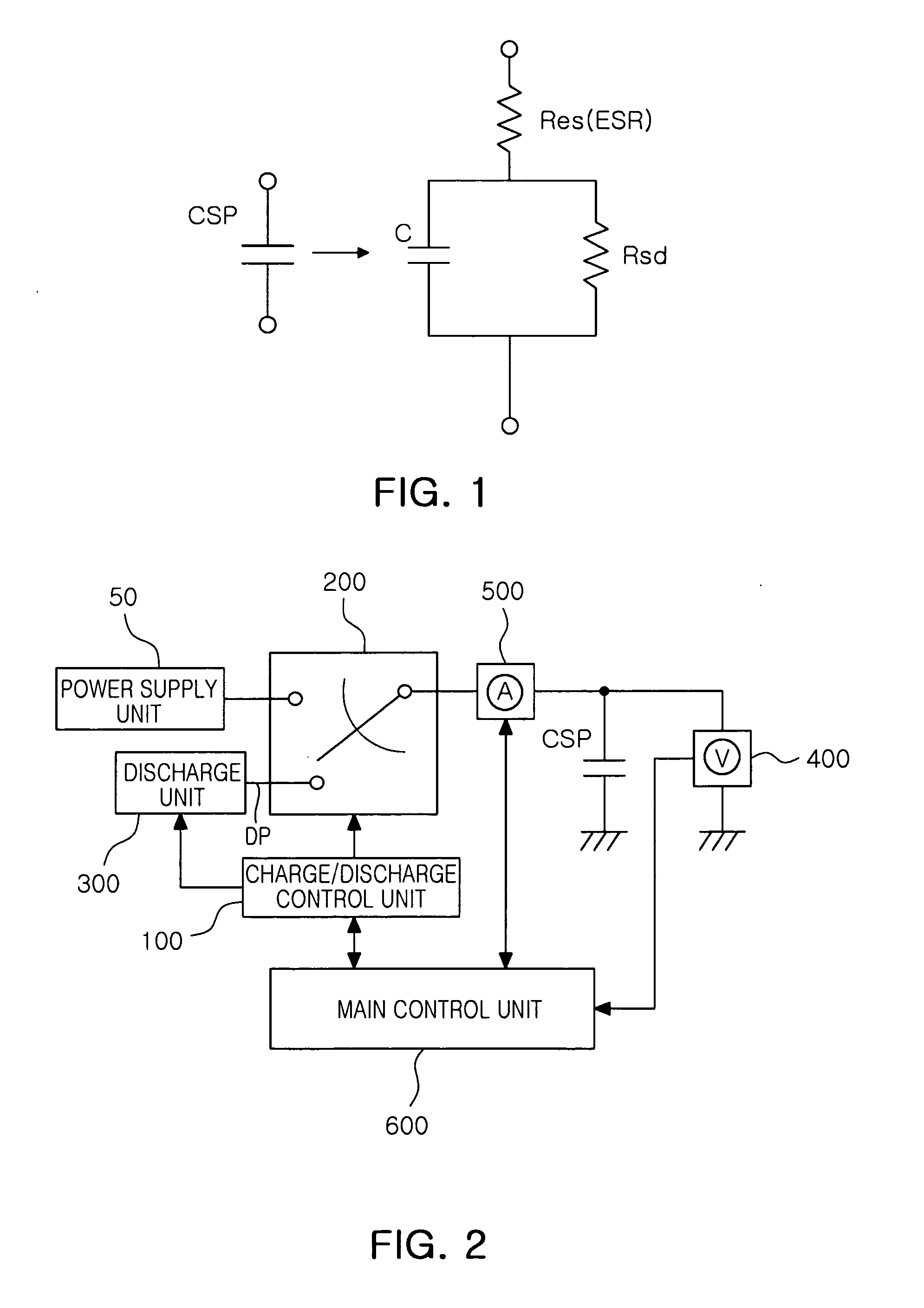
[0038]FIG. 2 is a block diagram of an apparatus for evaluating a capacitor according to an exemplary embodiment of the present invention. Referring to FIG. 2, an apparatus for evaluating a capacitor according to an exemplary embodiment of the present invention may be configured to include a charge / discharge control unit 100 that controls charge and discharge, a charge / discharge switch 200 that selects a connection between a capacitor CSP to be measured and a power supply unit 50 or a connection betw...


PUM


Abstract

There is provided an apparatus for evaluating a capacitor, including: a charge / discharge control unit 100 that controls charge and discharge, a charge / discharge switch 200 that selects a connection between a capacitor CSP to be measured and a power supply unit 50 or a connection between the capacitor CSP and a discharge path DP, a discharge unit 300 that is connected to the discharge path DP and provides discharge resistance for the discharge of the capacitor CSP, a voltage measuring unit 400 that measures the voltage of the capacitor CSP, a current measuring unit 500 that measures the charge current or discharge current of the capacitor CSP, and a main control unit 600 that controls the charge and discharge through the charge / discharge control unit 100 and obtains equivalent series resistance Res, capacitance C and self discharge resistance Rsd during the charge and discharge.

Description

CROSS-REFERENCE TO RELATED APPLICATIONS[0001]This application claims the priority of Korean Patent Application No. 10-2009-0119904 filed on Dec. 4, 2009, in the Korean Intellectual Property Office, the disclosure of which is incorporated herein by reference.BACKGROUND OF THE INVENTION[0002]1. Field of the Invention[0003]The present invention relates to an apparatus and a method for evaluating a large capacity capacitor that can be applied to automobiles or wind power generation, and more particularly, to an apparatus and a method for evaluating a capacitor that can automatically measure the ESR (equivalent series resistance), capacitance and self discharge resistance of the capacitor, and rapidly perform the measurement.[0004]2. Description of the Related Art[0005]Recently, there has been increasing demand for a large capacity capacitor that features high output for hybrid automobiles, wind power generation, etc. Further, it is necessary to evaluate the characteristics of such a lar...

Claims


Application Information

Patent Timeline
Patent Type & Authority Applications(United States)
IPC IPC(8): G01R27/26H01G13/00
CPCG01R31/028G01R27/2605G01R31/64G01R27/02
Inventor CHAE, KYOUNG SOOJUNG, HYUN CHULLEE, HEE BUM
Owner SAMSUNG ELECTRO MECHANICS CO LTD
Learn More