Heat sensor responsive to electrical overloads

US20110134575A1Active Publication Date: 2011-06-09WARD MICHAEL

Image

  • Heat sensor responsive to electrical overloads
  • Heat sensor responsive to electrical overloads
  • Heat sensor responsive to electrical overloads

Examples


Embodiment Construction

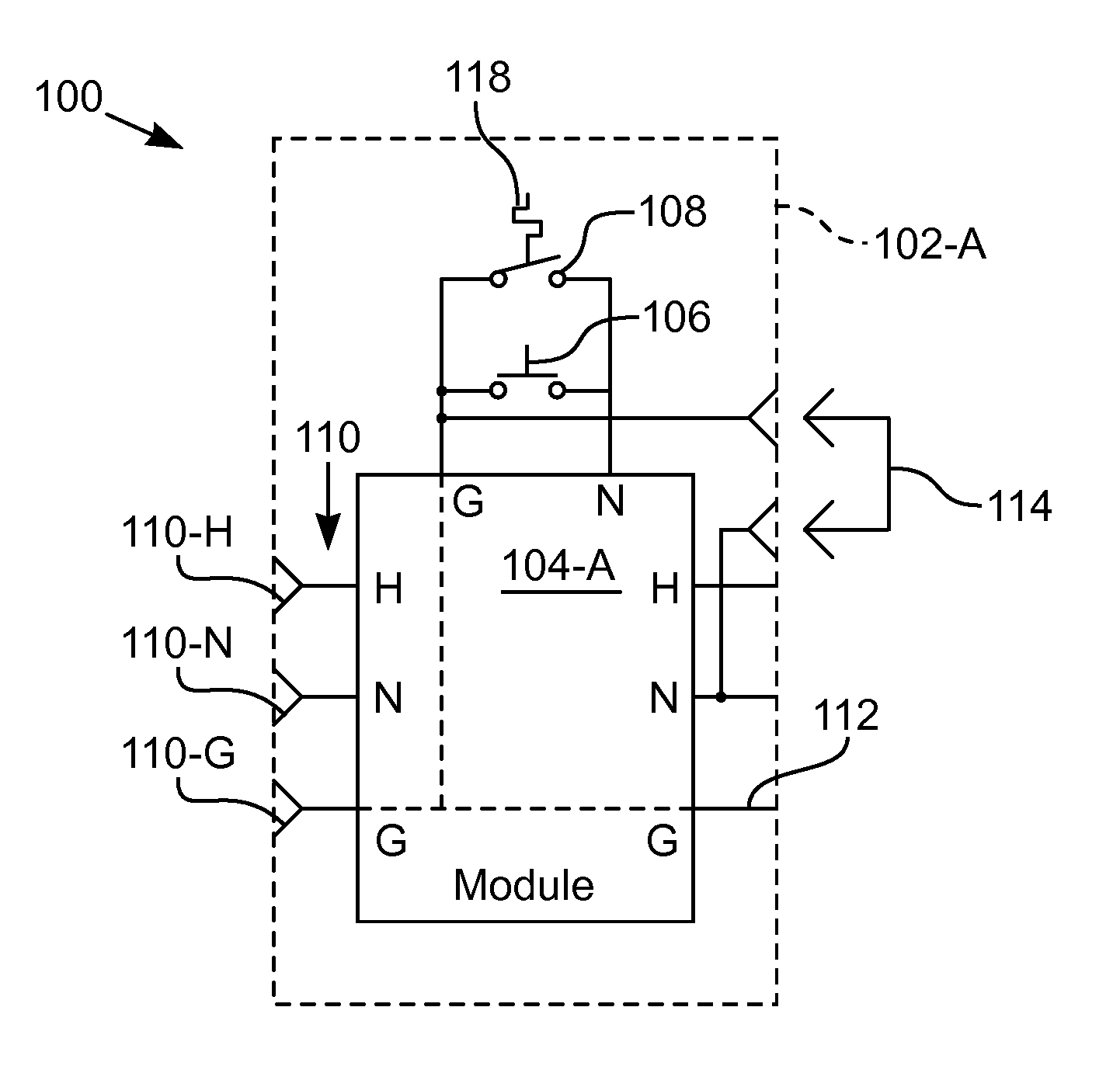
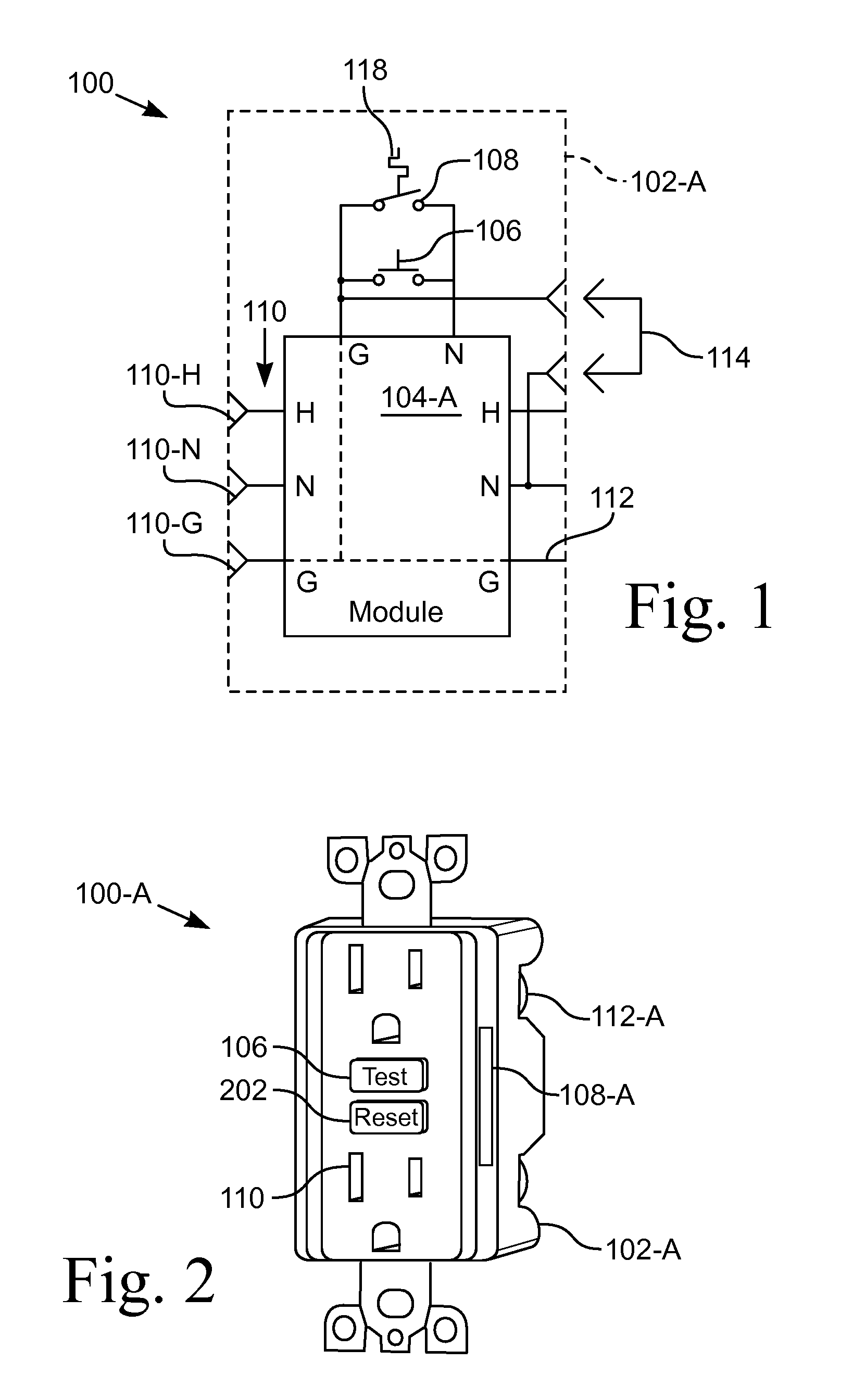
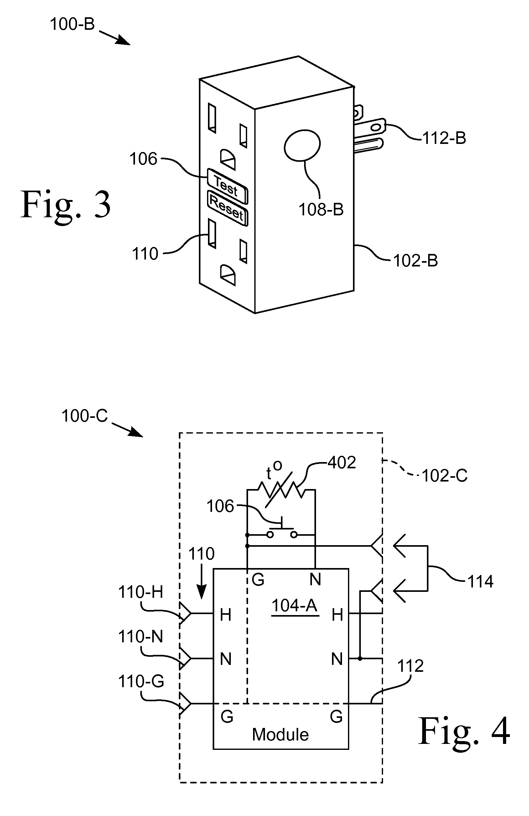
[0026]Apparatus for interrupting an electrical circuit upon detecting a high temperature is disclosed. The high temperature is greater than the wire / cable temperature rating and less than the melting temperature of the insulation. The high temperature is often caused by misuse of the receptacle 102, such as by using an adapter to plug multiple devices into the receptacle 102 and / or using frayed or damaged cords. As used herein, the suffixes, for example, -A and -B, appended to a reference number indicate an embodiment of a component. When the reference number is used without the suffix, the generic component is being referenced.

[0027]FIG. 1 illustrates a schematic diagram of one embodiment of a heat actuated interrupter receptacle device 100. A receptacle 102-A houses an interrupting module 104-A that includes a set of input, or line, connections 112, such as those that connect to a power source, and a set of output, or load, connections 110, such as those of a receptacle socket. Th...


PUM


Abstract

Apparatus for detecting an overheating condition at an electrical power device and automatically breaking the circuit when the temperature exceeds a setpoint value. In various configurations the device is a receptacle adapted to be used in a wall mounted box or a receptacle unit that is plugged into an existing receptacle. A temperature sensor is wired parallel to a normally open test switch on a ground fault circuit interrupter or other circuit interrupting device. The temperature switch is responsive to the temperature local to the receptacle, such as is caused by poor connections to or in the receptacle or a near-overload condition. The temperature setpoint is less than the melting temperature of the insulation of the electrical wiring. The temperature sensor is a thermistor with a negative temperature coefficient that allows current to flow thereby latching the interrupting device in a tripped position until the device is reset for reuse.

Description

CROSS-REFERENCE TO RELATED APPLICATIONS[0001]This application is a continuation-in-part of prior application Ser. No. 12 / 632,095, filed Dec. 7, 2009.STATEMENT REGARDING FEDERALLY SPONSORED RESEARCH OR DEVELOPMENT[0002]Not ApplicableBACKGROUND OF THE INVENTION[0003]1. Field of Invention[0004]This invention pertains to a temperature sensor that detects high temperature conditions caused by electrical overloads. More particularly, this invention pertains to a temperature sensor that cooperates with a circuit that interrupts the power circuit to the electrical appliance based on the temperature proximate the temperature sensor.[0005]2. Description of the Related Art[0006]Every year there are thousands of electrical fires in homes. Hundreds die every year in these fires, with many more injured. Some of these fires are caused by electrical system failures and defective appliances. But, many more of these fires are caused by the misuse and poor maintenance of electrical appliances, incorre...

Claims


Application Information

Patent Timeline
09 Jun 2011
Publication
US20110134575A1
IPC
H02H5/04; H02H3/16; G01K13/00
CPC
G01K3/005; G01K13/00; H02H5/042; H01H2083/206; H02H3/26; H01H83/20
Inventors
WARD, MICHAEL J.; CONTRERAS, ALEPH RUIZ