Cleaning blade, and image forming apparatus and process cartridge using the same

Active Publication Date: 2011-06-09
RICOH KK
View PDF12 Cites 36 Cited by
  • Summary
  • Abstract
  • Description
  • Claims
  • Application Information

AI Technical Summary

Benefits of technology

For these reasons, the present inventors recognize that a need exists for a cleaning blade having good durability and superior cleaning capabil

Problems solved by technology

However, although successful in prolonging the working life of the image bearing member, the frequency of replacement thereof remains unchanged unless the working life of the cleaning blade is also prolonged.
Therefore, the working life of the cleaning blade becomes a bottleneck, in that it necessitates replacement of the entire of the process cartridge even though the image bearing member is not completely worn out.
However, the polymerized toner is difficult to sufficiently remove from the surface of the image bearing member with the cleaning blade, thereby causing a problem with regard to the cleaning performance.
This difficulty of removal occurs because the polymerized toner particles have a near-spherical form and are of such a small size that they slip through the small gap between the cleaning blade and the image bearing member.
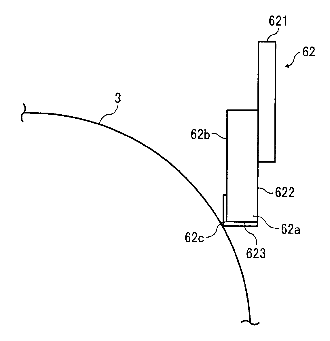
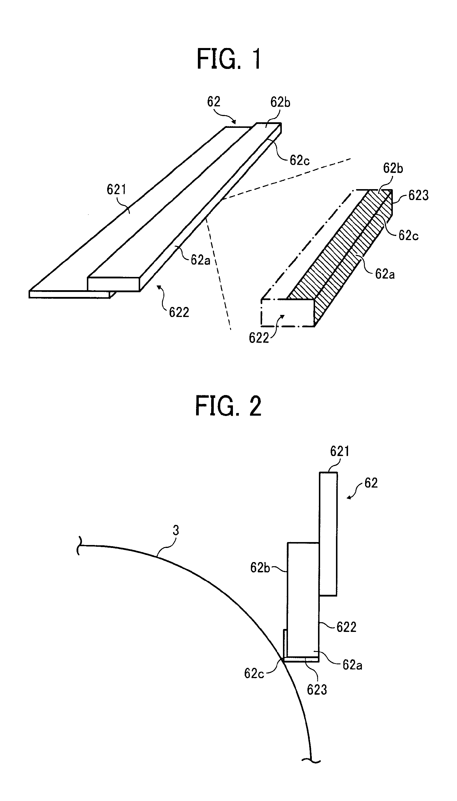
Once part of the front edge portion 262c has chipped off, the cleaning blade no longer removes the toner sufficiently, resulting in poor cleaning performance, meaning the end of the working life of the cleaning blade.
However, although suitable for an image bearing member having a smooth surface made of a material such as amorphous silicon, this cleaning blade chips off at an early stage and causes poor cleaning performance in most cases when it cleans a roughened surface of an image bearing member such as an organic pho

Method used


Image

  • Cleaning blade, and image forming apparatus and process cartridge using the same
  • Cleaning blade, and image forming apparatus and process cartridge using the same
  • Cleaning blade, and image forming apparatus and process cartridge using the same

Examples


example 1

A surface layer is formed at the front end of the contact portion by spray coating.

The used spray device is PC WIDE 308 (manufactured by Olympos). The discharging amount from the spray gun of the spray device is adjusted to obtain a predetermined layer thickness by moving the spray gun at 7 mm / s with a pressure of 0.5 MPa from 40 mm away from the front end of the contact portion.

Thereafter, the surface is left undone for five minutes followed by 10 minute vacuum drying at 30° C. followed by irradiation of UV light (1,000 mj / cm2) to polymerize the impregnated acylate monomers while forming the surface layer.

The drugs for use in the spray coating liquid are subject to vacuum freeze-degassing treatment to remove oxygen.

Spray coating and drying are conducted in an environment in which the oxygen concentration is 100 ppm or less.

The results are as follows:

Acrylate polymer 1 (polymerized Acrylate material 1)Thickness of surface layer  1 μmImpregnation depth of Acrylate polymer 17.5 μm

example 2

A surface layer is formed on the front end of the contact portion in the same manner as in Example 1 except that Acrylate material 2 is used instead of Acrylate material 1.

The results are as follows:

Acrylate polymer 2 (polymerized Acrylate material 2)Thickness of surface layer 0.6 μmImpregnation depth of Acrylate polymer 210.5 μm

example 3

A surface layer is formed on the front end of the contact portion is formed in the same manner as in Example 1 except that Acrylate material 3 is used instead of Acrylate material 1.

The results are as follows:

Acrylate polymer 3 (polymerized Acrylate material 3)Thickness of surface layer 0.6 μmImpregnation depth of Acrylate polymer 313.5 μm


PUM


Abstract

A cleaning blade for use in an image forming apparatus including a holder, and an elastic blade attached to the holder and in contact with an image bearing member, the elastic blade being impregnated with an acrylate polymer from at least one surface to a depth of from 5 to 100 μm.

Description

BACKGROUND OF THE INVENTION1. Field of the InventionThe present invention relates to a cleaning blade, and an image forming apparatus and a process cartridge using the cleaning blade.2. Description of the Related ArtIn image forming apparatuses using electrophotography, images are formed through processes of charging, irradiation, development, transfer etc. applied to an image bearing member.Ordinarily, corona products produced in the charging process that remain on the surface of the image bearing member, and toner or its components remaining on the surface of the image bearing member after the transfer process, are removed by a cleaning process.In terms of improving the reliability of the image forming apparatus, an image bearing member formed of an inorganic material such as amorphous silicon, or a highly durable image bearing member that has a surface layer in which an acrylate-based material or inorganic particulates are dispersed, are now widely used. These image bearing membe...

Claims


Application Information

Patent Timeline
IPC IPC(8): G03G21/00
CPCG03G21/0017
Inventor KABATA, TOSHIYUKISHIONOIRI, MOMOKOGONDOH, MASANOBUSAKON, YOHTAOHMORI, MASAHIRO
Owner RICOH KK
Why Eureka
Try Eureka