
Vacuum transfer apparatus

a vacuum transfer and vacuum technology, applied in the direction of transportation and packaging, manufacturing tools, arms, etc., can solve the problems of increasing the size of the vacuum vessel and the inability so as to reduce the volume required for the placement reduce the size of the vacuum transfer apparatus. the effect of the entire siz

Inactive Publication Date: 2011-06-09
CANON ANELVA CORP
View PDF8 Cites 7 Cited by
  • Summary
  • Abstract
  • Description
  • Claims
  • Application Information

AI Technical Summary

Benefits of technology

[0012]In the above related art, in order to increase the transfer amount in the vertical direction in the lifting operation, it is essential to secure the volume for the vertical motion outside the vacuum vessel. The constitution disclosed in the Patent Document 2 can avoid the increase in size of the metallic bellows disposed outside the vacuum vessel. On the other hand, in the constitutions disclosed in the Patent Document 1 and 2, the driving shaft with a length realizing the necessary transfer amount in the vertical direction is disposed outside the vacuum vessel, whereby there are such disadvantages that the vacuum vessel is increased in size, and the volume required for placement of the vacuum transfer apparatus cannot be reduced.
[0015]According to this invention, the two-dimensional transfer means and the support means are disposed inside the vacuum chamber, whereby the transfer amount (lifting amount) of a transferred object in a direction vertical to the transfer direction, by the two-dimensional transfer means is increased, and, at the same time, a volume required for placement of the vacuum transfer apparatus can be reduced. Therefore, this invention can reduce the entire size of the vacuum transfer apparatus.

Problems solved by technology

On the other hand, in the constitutions disclosed in the Patent Document 1 and 2, the driving shaft with a length realizing the necessary transfer amount in the vertical direction is disposed outside the vacuum vessel, whereby there are such disadvantages that the vacuum vessel is increased in size, and the volume required for placement of the vacuum transfer apparatus cannot be reduced.

Method used


Image

  • Vacuum transfer apparatus
  • Vacuum transfer apparatus
  • Vacuum transfer apparatus

Examples


Embodiment Construction

[0045]Hereinafter, an embodiment of this invention will be described with reference to the drawings.

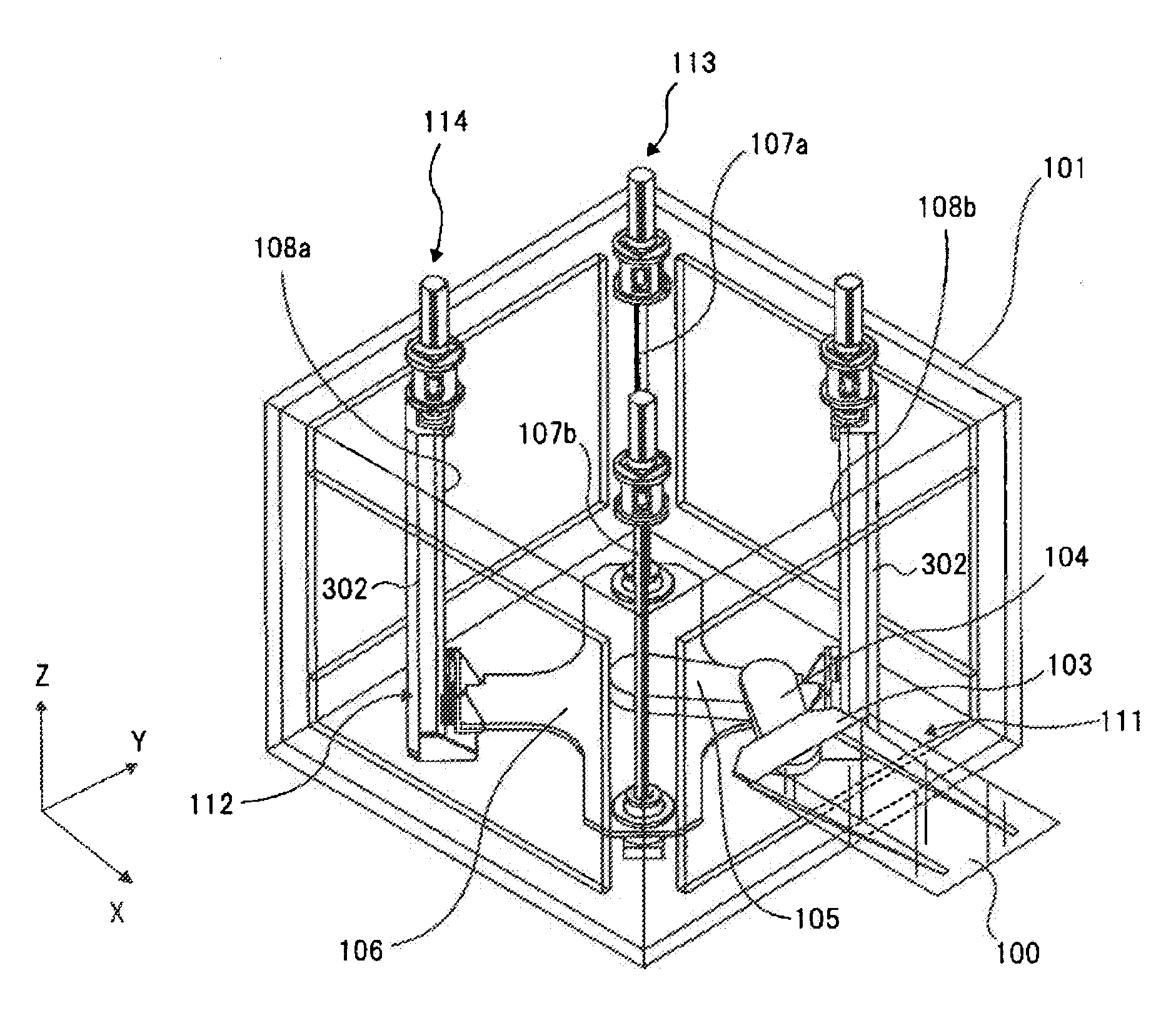
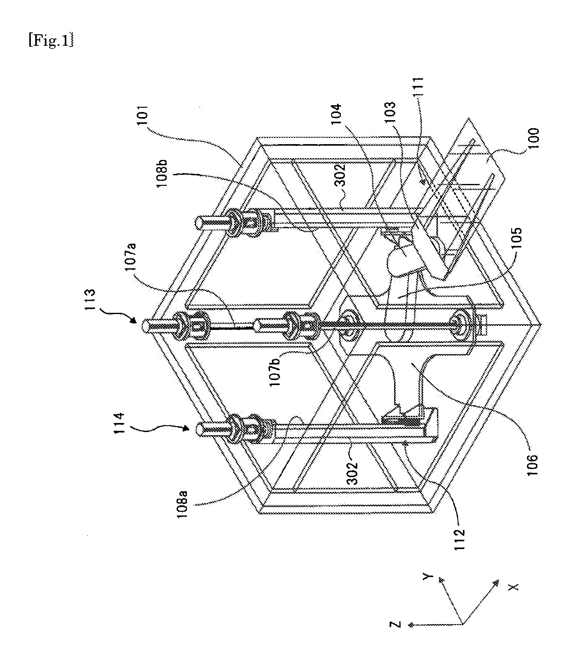
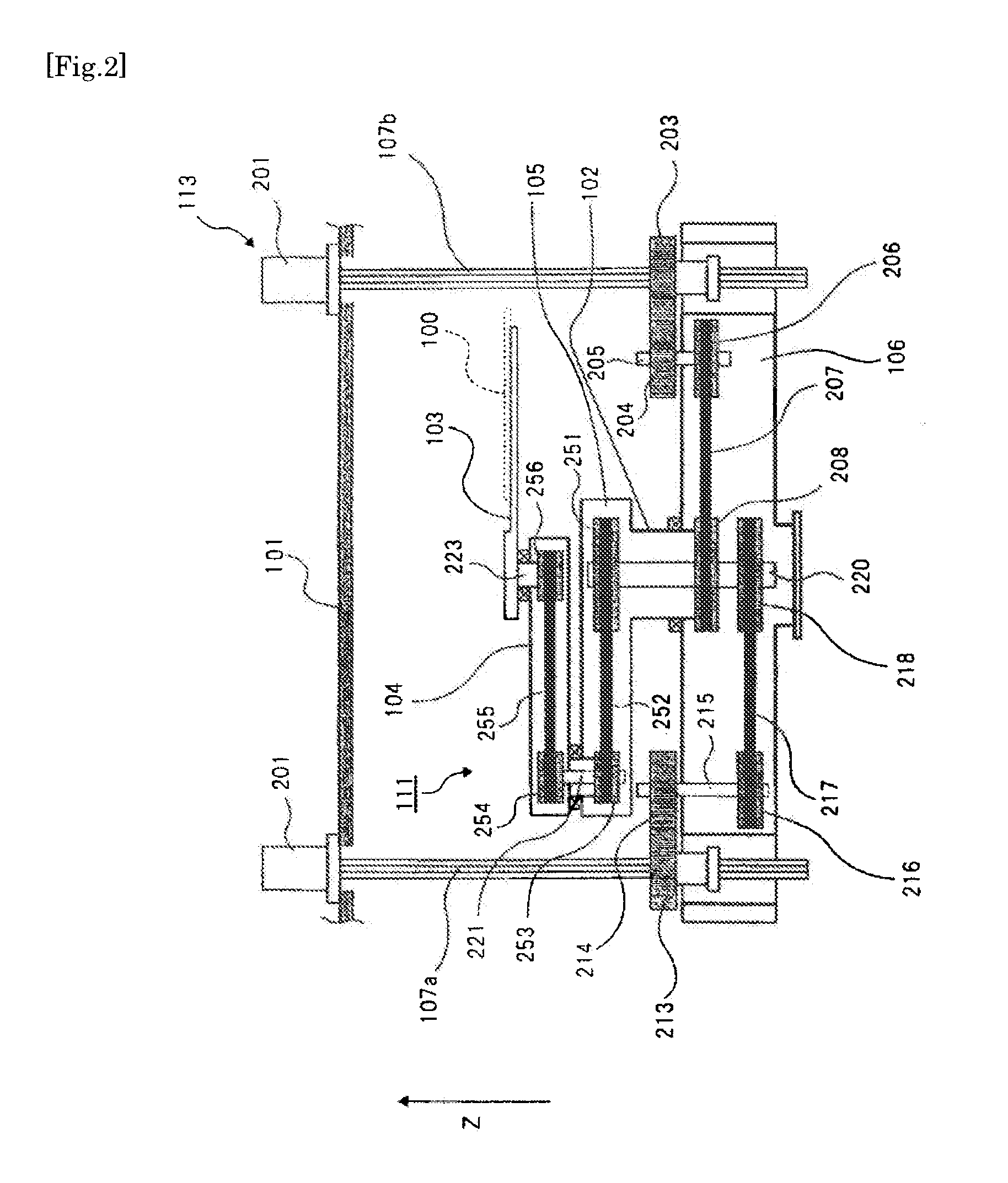
[0046]FIG. 1 is a perspective view showing a schematic constitution of a vacuum transfer robot of the present embodiment as a vacuum transfer apparatus according to this invention. FIG. 2 is a cross-sectional view showing a schematic constitution of a horizontal transfer mechanism and a horizontal driving part of the vacuum transfer robot of this embodiment. In this embodiment, a two-dimensional direction is a horizontal plane direction, and a direction vertical thereto is a vertical direction.

[0047]As shown in FIG. 1, the vacuum transfer robot of this embodiment is used for transferring a substrate 100 in three axis directions. The substrate 100 is a transferred object mounted with a device structure for a semiconductor and various displays. The vacuum transfer robot includes a horizontal transfer mechanism 111 which is two-dimensional transfer means for transferring the substrate 10...


PUM


Abstract

Disclosed is a vacuum transfer apparatus, which can increase a transfer amount in a vertical direction of a transferred object and can reduce a volume required for placement of the vacuum transfer apparatus, whereby contributing to the size reduction of the vacuum transfer apparatus.The vacuum transfer apparatus includes a horizontal transfer mechanism 111 for transferring a substrate 100 in a horizontal direction, a vertical transfer mechanism 112 for transferring the substrate 100 in a vertical direction, a vacuum vessel 101 including the horizontal transfer mechanism 111 and the vertical transfer mechanism 112, a horizontal driving part 113 having X and Y axis direction driving shafts 107a and 107b disposed in the vacuum vessel 101 and driving the horizontal transfer mechanism 111 by means of the X and Y axis direction driving shafts 107a and 107b, and a vertical driving part 114 having Z axis direction driving shafts 108a and 108b disposed in the vacuum vessel 101 and driving the vertical transfer mechanism 112 by means of the Z axis direction driving shafts 108a and 108b.

Description

TECHNICAL FIELD [0001]This invention relates to a vacuum transfer apparatus for transferring a transferred object, such as a substrate, in a vacuum chamber in three axis directions.BACKGROUND ART [0002]For example, a semiconductor manufacturing apparatus and a flat panel display manufacturing apparatus use a vacuum transfer apparatus serving as transfer means for transferring a substrate in a vacuum chamber constituted of, for example, a vacuum vessel,[0003]As a representative configuration of a substrate transfer apparatus for transferring a substrate in a vacuum chamber, there has been known a configuration disclosed in FIG. 10 of Patent Document 1.[0004]In the Patent Document 1, a driving system used in a power and control is disposed outside a vacuum vessel and is connected through a vacuum flange. The vacuum vessel contains only an arm part for actually holding and transferring a substrate, and the driving system and a transferring system are separated by the vacuum vessel.[000...

Claims


Application Information

Patent Timeline
IPC IPC(8): H01L21/677B25J9/00
CPCB25J9/042B25J9/104B25J18/06H01L21/67766B65G49/068B65G2249/02H01L21/67742B65G49/067B25J9/0021
Inventor SHUNSUKE, TAMAYAWATARU, ITOU
Owner CANON ANELVA CORP
Learn More