Polishing head and polishing apparatus

a polishing apparatus and polishing head technology, applied in the field of polishing heads, can solve the problems of inability to obtain stable flatness of workpieces, difficulty in adjustment, and inability to change the polishing profile, and achieve the effect of easy change, good flatness and good flatness

Active Publication Date: 2011-06-09
SHIN-ETSU HANDOTAI CO LTD +1
View PDF20 Cites 5 Cited by
  • Summary
  • Abstract
  • Description
  • Claims
  • Application Information

AI Technical Summary

Benefits of technology

[0024]In this manner, when the workpiece is polished by using the polishing apparatus provided with the polishing head according to the present invention, the polishing can be performed with giving a uniform polishing pressure to the workpiece, and even when there are somewhat the variation of the thickness of the workpiece and the template, good flatness and polishing stock removal uniformity can be always secured. In the event that the shape of the workpiece before the polishing is not flat, the polishing profile can be readily changed by adjusting the pressure of each of the sealed spaces on the basis of the shape thereof, and the shape of the workpiece can be modified into a flat shape.
[0025]In the polishing head according to the present invention, the space is divided by at least one annular wall concentric with the rigid ring to form a plurality of sealed spaces; an outer diameter of at least one inside sealed space of the plurality of sealed spaces divided by the annular wall is formed so as to be equal to or more than a diameter of a flatness-guaranteed region of the workpiece; and the pressure adjustment mechanism separately controls pressure of each of the plurality of sealed spaces. The polishing can be therefore performed with giving a uniform polishing pressure to the workpiece, and even when there are somewhat the variation of the thickness of the workpiece and the template, good flatness and polishing stock removal uniformity can be always secured. In addition to this, in the event that the shape of the workpiece before polishing is not flat, the polishing profile can be readily changed by adjusting the pressure of the sealed space on the basis of the shape thereof, and the shape of the workpiece can be modified into a flat shape.

Problems solved by technology

When the workpiece W is polished by using the polishing head 101 holing the workpiece W on the rubber film 103 as described above, the flatness and the polishing stock removal uniformity of the whole workpiece W may be improved in some cases, but there is a problem that stable flatness of the workpiece W cannot be obtained, for example, due to an influence of variation of the thickness of the workpiece and the template.
Moreover, in the event that an original shape of the workpiece W before polishing is not flat, it is necessary to adjust a polishing profile in order to modify the shape of the workpiece W. A conventional polishing head by the rubber-chuck method, however, cannot readily change the polishing profile, and such an adjustment is thus difficult.

Method used


Image

  • Polishing head and polishing apparatus
  • Polishing head and polishing apparatus
  • Polishing head and polishing apparatus

Examples


example 1

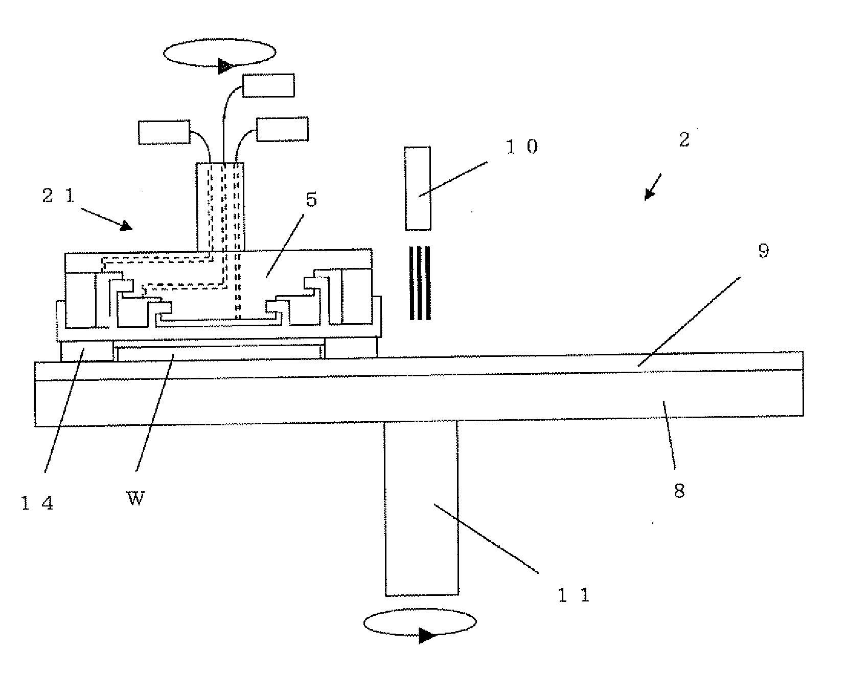
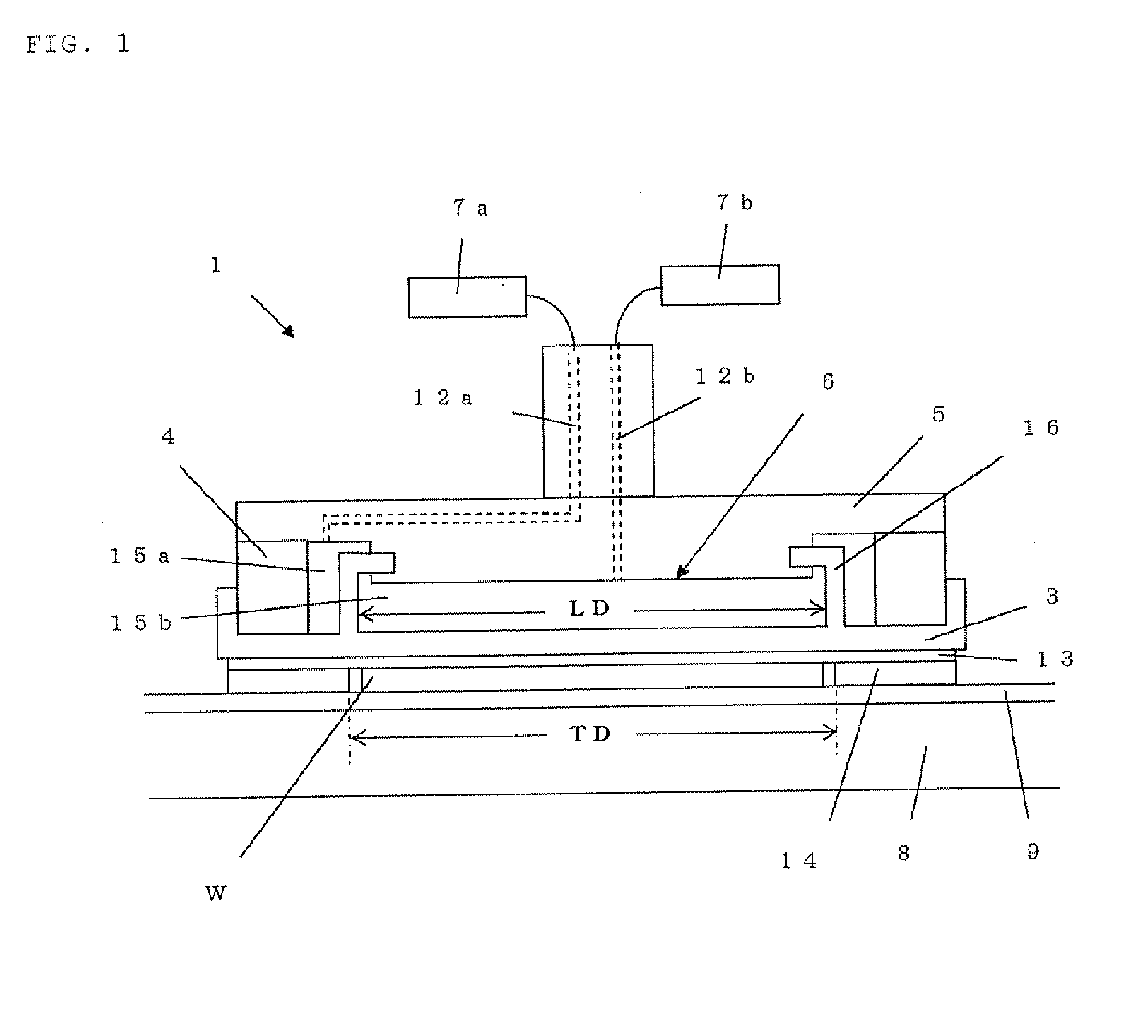
[0084]The polishing head 1 according to the present invention as shown in FIG. 1 and the polishing apparatus provided with the polishing head were used to polish the workpiece W, and the pressure distribution of the workpiece during the polishing and the polishing stock removal uniformity were evaluated.

[0085]The structure of the used polishing head 1 was as follows.

[0086]The rigid ring 4 had an outer diameter of 358 mm and an inner diameter of 320 mm, and was made of SUS. The rubber film 3 was made of silicone rubber having a hardness of 70 (based on JIS K6253), and had a thickness of 1 mm.

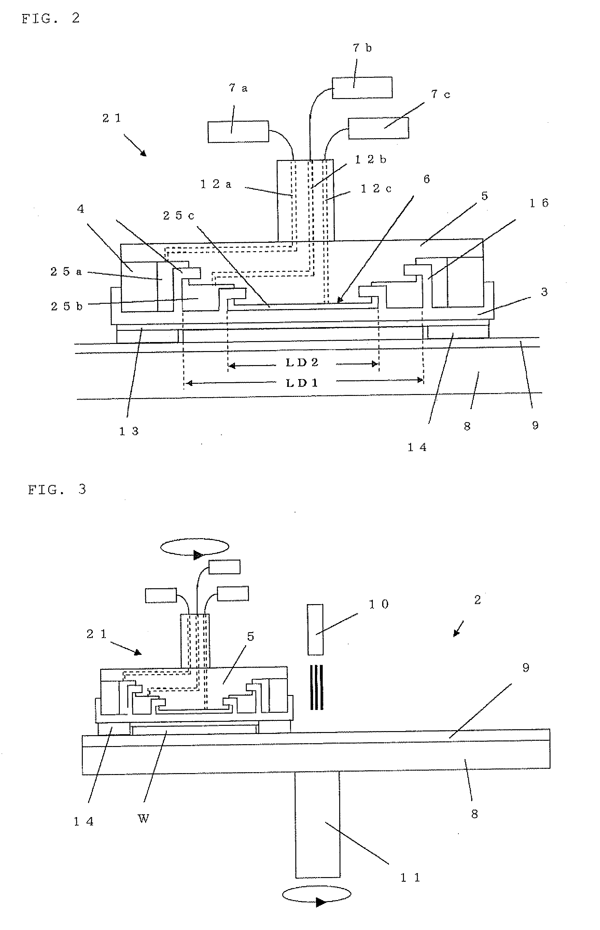
[0087]In addition, the space 6 was divided by the annular wall 16 concentric with the rigid ring 4 to form two sealed spaces 15a and 15b. The outer diameter LD of the inside sealed space 15b was 300 mm. Here, the wall 16 had a thickness of 1 mm, and was made of the same material as the rubber film 3.

[0088]Moreover, the backing pad 13 was attached to be provided on the lower face of the rubber fil...

example 2

[0100]A wafer was polished as with Example 1 except for changing the pressure P2 of the sealed space 15a to 15 Kpa, 16.13 KPa, 16.5 KPa, and 18 KPa, and the polishing pressure distribution was evaluated.

[0101]FIG. 5 shows the result. As shown in FIG. 5, it is confirmed that the polishing pressure at the outer circumferential portion of the wafer can be changed and the polishing stock removal uniformity can be adjusted by changing the pressure P2.

example 3

[0102]A wafer was polished as with Example 1 except for using the polishing head 1 with the inside sealed space 15b having an outer diameter LD of 296 mm, 301 mm, 302 mm, 304 mm, and 308 mm, and for changing the pressure P2 of the sealed space 15a in the range of 15 to 30 KPa, and the polishing pressure distribution was evaluated.

[0103]FIG. 6 shows the result of the relationship between the polishing stock removal uniformity and the pressure P2 of the sealed space 15a in the case of an outer diameter LD of 304 mm, and 308 mm. As shown in FIG. 6, it was revealed that the polishing stock removal uniformity can be improved by adjusting the pressure P2. FIG. 7 shows the results of minimum values of the polishing stock removal uniformity in the case of each outer diameter LD. As shown in FIG. 7, it was revealed that each polishing stock removal uniformity was improved in comparison with the result of the later-explained Comparative Example 2, and they were a good result of 2.5% or less.


PUM


Abstract

A polishing head for holding a workpiece when a surface of the workpiece is polished and a polishing apparatus provided with the polishing head, and more particularly a polishing head for holding the workpiece on a rubber film and a polishing apparatus provided with the polishing head. The polishing head and the polishing apparatus provided with the polishing head that can adjust the polishing profile on the basis of the shape of the workpiece before polishing and can stably obtain good flatness.

Description

TECHNICAL FIELD[0001]The present invention relates to a polishing head for holding a workpiece when a surface of the workpiece is polished and a polishing apparatus provided with the polishing head, and more particularly to a polishing head for holding the workpiece on a rubber film and a polishing apparatus provided with the polishing head.BACKGROUND ART[0002]As an apparatus for polishing a surface of a workpiece such as a silicon wafer, there are a single-side polishing apparatus, in which the workpiece is polished by each side, and a double-side polishing apparatus, in which the both sides of the workpiece are polished at the same time.[0003]For example as shown in FIG. 10, a common single-side polishing apparatus comprises a turn table 88 onto which a polishing pad 89 is attached, a polishing agent supply mechanism 90, a polishing head 81 and the like. This polishing apparatus 82 polishes a workpiece W by holding the workpiece W with the polishing head 81, supplying a polishing ...

Claims


Application Information

Patent Timeline
Patent Type & Authority Applications(United States)
IPC IPC(8): B24B37/04H01L21/304B24B37/005B24B37/30
CPCB24B37/30
Inventor MASUMURA, HISASHIHASHIMOTO, HIROMASAMORITA, KOUJIKISHIDA, HIROMIARAKAWA, SATORU
Owner SHIN-ETSU HANDOTAI CO LTD
Why Eureka
Try Eureka