Injection device for soft-tissue augmentation fillers, bioactive agents and other biocompatible materials in liquid or gel form

a technology of injection device and soft tissue, which is applied in the field of injection device for soft tissue augmentation fillers, bioactive agents and other biocompatible materials in liquid or gel form, can solve the problems of striking difficulty in striking difficulty in properly using, and difficulty in properly controlling the injection rate, etc., and achieves the effect of being easily maneuverable by a physician and being sufficiently lightweigh

Active Publication Date: 2011-06-09
ALLERGAN INC
View PDF91 Cites 53 Cited by
  • Summary
  • Abstract
  • Description
  • Claims
  • Application Information

AI Technical Summary

Benefits of technology

[0009]Advantageously, many of the present devices are structured to provide highly controlled, precisely quantified injection of materials through very fine needles, wherein such materials are extremely difficult to inject, or even impossible to inject, using conventional techniques and manually operated syringes.

Problems solved by technology

One monumental problem with traditional syringes is that they are difficult to properly utilize due to their poor ergonomics.
Another problem commonly encountered when using hypodermic syringes with manual plungers is the difficulty of controlling the rate of injection, especially when the injectable substance is highly viscous, the tissue being injected into is dense or a combination of the two.
In such cases, the force required to extrude the injectable substance into a patient makes controlling the rate of injection and the handling of the syringe strikingly difficult.
Commonly, unreliable injection speeds are encountered as well as patient pain associated with additional axial force on the syringe in an effort to supply sufficient extrusion force to the syringe's plunger to force the injectable substance out of the needle into the patient's tissues.
Another problem with injectable substances relates to reconstitution prior to injection.
Patient discomfort with injections can lie in anticipation of the injection itself, and therefore, lead to a tense patient and hence more discomfort upon injection.
As such, manually reconstituting an injectable just prior to injection can cause both mental and physical discomfort for a patient.

Method used


Image

  • Injection device for soft-tissue augmentation fillers, bioactive agents and other biocompatible materials in liquid or gel form
  • Injection device for soft-tissue augmentation fillers, bioactive agents and other biocompatible materials in liquid or gel form
  • Injection device for soft-tissue augmentation fillers, bioactive agents and other biocompatible materials in liquid or gel form

Examples


example 1

[0101]Extrusion experiments were performed on 0.8 mL Schott TopPac® (SCHOTT North America, Inc., Lebanon, Pa.) syringe fitted with a Tyco 30 G×½″ needle. Juvèderm™ Ultra (Allergan Inc., Irvine, Calif.) was extruded from the needle to assess the force needed to extrude the highly viscous hyaluronic acid-based dermal filler through a 30 G needle. The results in Table 1 show the results of the experiments.

TABLE 1ApproximatePlunger RatePlunger RateInjection Rate*Approximate Force(mm / min)(mm / sec)(mL / sec)Required (N)200.3330.00623500.8330.015351001.6670.029471502.5000.04460*Schott 0.8 mL syringe, the gradient is: 5.7 mm is approximately 0.1 mL

[0102]For example, to inject the total contents of the syringe at a rate of 0.006 mL / sec, the plunger must travel approximately 46 mm in a time of approximately 2.3 min (approximate plunger rate of 20 mm / min).

[0103]Results showed that depending on the desired injection rate, large forces are required to advance the plunger and inject the viscous derm...

example 2

[0104]This example refers to the device 100 depicted in FIG. 1A-1C, the electronic display screen 400 in FIG. 4, and the injection components of the inner body depicted in FIG. 5.

[0105]The operator turns on the device 100 by depressing power button 105. The electronic display 106 (which may comprise screen 400 in FIG. 4) will power on and indicate the device status as ‘cartridge not loaded.’ The device is then set-up to provide an audible beep to alert the operator as to the status ‘cartridge not loaded.’ The operator proceeds to slide the cartridge into the hole at the front of the device in cap 107. The hole in cap 107 reveals the cartridge chamber in the inner body of the device. The cartridge is slid into the device until it clicks in place. The device then reads the RFID off the cartridge and presents the appropriate data on display 106. Once the data is uploaded from the RFID and processed by the device, ‘Ready’ will be presented on display 106. The operator can then adjust th...

example 3

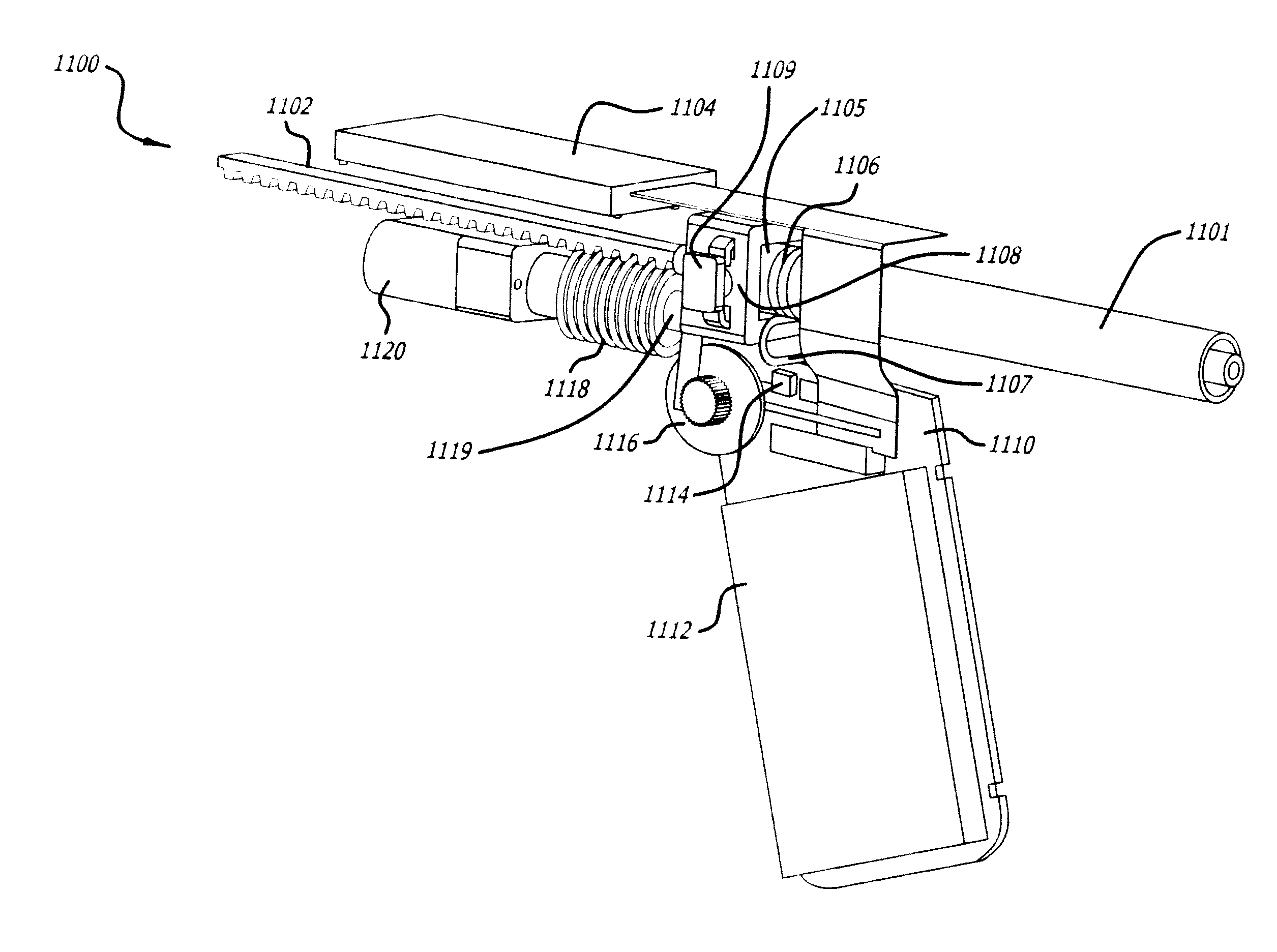
[0107]This example refers to the device 100 depicted in FIG. 1A-1C, the electronic display screen 400 in FIG. 4, and the components of the inner body depicted in FIG. 6.

[0108]The operator turns on the device 100 by depressing power button 105. A red LED illuminates indicating the device is not ready for injection. The electronic display 106 will power on and indicate the device status as ‘cartridge not loaded.’ The device can be set-up to provide an audible beep to alert the operator as to the status ‘cartridge not loaded.’ The operator proceeds to slide a cartridge of dried botulinum toxin Type A into the hole at the front of the device in cap 107. The hole in cap 107 reveals the cartridge chamber in the inner body of the device. The cartridge is slid into the device until it clicks in place. The device then reads the RFID off the cartridge and presents the appropriate data on display 106. Once the data is uploaded from the RFID and processed by the device, the device indicates to ...


PUM


Abstract

Described herein are injection devices capable of automatically injecting substances into the soft tissue of a patient. The devices can inject low to high viscosity materials at predetermined, user selected injection rates, allowing the operator more control than a traditional syringe. The devices can allow mixing of more than one substance and / or reconstitution of a solid substance for injection. The injection devices described herein can allow the operator to easily inject one or more low to high viscosity liquid or gel soft-tissue augmentation fillers, one or more drugs, one or more other biocompatible materials, or combinations thereof.

Description

RELATED APPLICATION[0001]This application claims the benefit of U.S. Provisional Patent Application No. 61 / 057,703 filed on May 30, 2008, and U.S. Provisional Patent Application No. 61 / 074,538 filed on Jun. 20, 2008, the disclosure of each of which is incorporated herein in its entirety by this specific reference.FIELD OF THE INVENTION[0002]The present invention relates to devices useful for injecting soft-tissue augmentation fillers, bioactive agents and other biocompatible materials.BACKGROUND OF THE INVENTION[0003]The injection of bioactive agents and tissue augmentation fillers is quite commonplace. Commonly, bioactive agents and tissue augmentation fillers are injected manually using traditional hypodermic syringes with manual plungers. One monumental problem with traditional syringes is that they are difficult to properly utilize due to their poor ergonomics.[0004]Another problem commonly encountered when using hypodermic syringes with manual plungers is the difficulty of cont...

Claims


Application Information

Patent Timeline
Patent Type & Authority Applications(United States)
IPC IPC(8): A61M5/20
CPCA61M5/19A61M2210/04A61M5/2053A61M5/24A61M5/2448A61M5/31575A61M5/427A61M5/46A61M2005/2006A61M2005/2411A61M2005/3125A61M2005/3128A61M2005/31588A61M2205/3569A61M2205/502A61M2205/586A61M2205/6045A61M2205/6063A61M2205/8206A61M2205/8212A61M2205/8237A61B5/150129A61M2205/19A61M2202/20A61M2202/09A61M2202/049A61M2202/0007A61M39/24A61M5/20A61M2205/8243A61M5/422A61M2205/36A61M2205/3606A61M2005/3126A61M2205/52A61M2205/587
Inventor MUDD, CHRISTOPHER S.TEZEL, AHMET
Owner ALLERGAN INC
Why Eureka
Try Eureka