Bone fixation with a bone plate attached to a fastener assembly
a technology of bone plate and fastener, which is applied in the field of bone plate fixation with a bone plate attached to a fastener assembly, can solve the problems of irritating or even tearing the tendon, the internal fixation of dorsally displaced bone fragments using bone plates is problematic, and the radius is susceptible to a variety of fractures and other dislocations
- Summary
- Abstract
- Description
- Claims
- Application Information
AI Technical Summary
Benefits of technology
Problems solved by technology
Method used
Image

Examples
example 1
Exemplary Fasteners for Retrograde Placement
[0096]This example describes exemplary fasteners for retrograde placement into bone and for coupling to a bone plate through a leading (distal) region of the fastener; see FIGS. 9-11.
[0097]FIG. 9 shows a bone screw 180 for retrograde placement into bone. The bone screw may include a head 182 joined to a shank 184. The head may have a larger cross-sectional dimension (such as diameter) than the shank and / or may include external or internal tool-engagement structure (e.g., a hexagonal recess 186) formed axially in and / or on the head for manipulation of the bone screw with a suitable driver. Shank 184 may include a nonthreaded region 186 proximally, adjacent the head, and a threaded region 188 (with an external thread 190) distally, spaced from the head. The nonthreaded region may include a stop structure, such as a shoulder 192 or an end to the external thread, that restricts advancement of the bone screw, particularly threaded advancement. ...
example 2
Guide Device to Assist Fastener Placement
[0101]This example describes an exemplary guide device 260 to assist forward and / or retrograde placement of fasteners into openings of a bone plate; see FIG. 12.
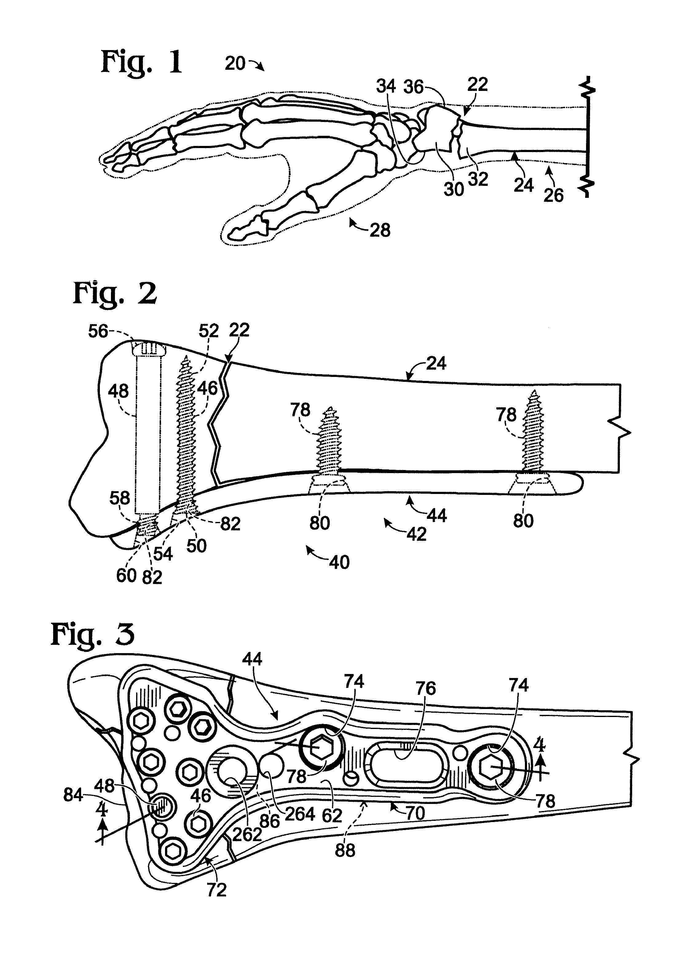
[0102]Guide device 260 may mount to an implant, such as bone plate 44, using one or more apertures, such as apertures 262, 264 (see FIG. 3), and a threaded coupling member 266. Apertures 262, 264 may be spaced from other openings, particularly (distal) locking openings of the bone plate. Accordingly, each distal opening and the internal thread therein may be accessible with the guide device mounted on the bone plate.
[0103]The mounted guide device may define a plurality of guide channels 268 aligned with each of the distal openings in the head portion of bone plate 44 (see FIG. 3). Each guide channel may define a guide path that is substantially aligned with the screw (helical) axis of a distal opening. The guide channel, with or without a suitable guide insert 270 (for example, to nar...
example 3
Retrograde Fixation of a Radial Styloid Fragment
[0104]This example describes exemplary fixation of a radial styloid fragment by retrograde placement of a fastener through the fragment and into engagement with a bone plate; see FIGS. 13 and 14.
[0105]FIG. 13 shows another exemplary configuration of system 40 (see FIGS. 2 and 3). In the present configuration, a styloid fragment 280 of the radius bone is fixed with a retrograde fastener 282, with a leading region 284 of the fastener disposed in threaded engagement with a distal opening 286 of bone plate 44. The fastener may have an oblique orientation relative to the long axis of the radius. A head 288 of the fastener thus may be disposed adjacent a distal end surface, a dorsal surface, and / or a lateral surface of the radius bone, among others.
[0106]FIG. 14 shows bone plate 44 and its coupled fasteners, including retrograde fastener 282, from the inner surface of the bone plate and without the radius bone. Any suitable combination of on...
PUM
 Abstract
Description
Claims
Application Information
 - R&D
- Intellectual Property
- Life Sciences
- Materials
- Tech Scout
- Unparalleled Data Quality
- Higher Quality Content
- 60% Fewer Hallucinations
Browse by: Latest US Patents, China's latest patents, Technical Efficacy Thesaurus, Application Domain, Technology Topic, Popular Technical Reports.
© 2025 PatSnap. All rights reserved.Legal|Privacy policy|Modern Slavery Act Transparency Statement|Sitemap|About US| Contact US: help@patsnap.com