Systems and methods for improving drivetrain efficiency for compressed gas energy storage and recovery systems

a technology of compressed gas energy storage and recovery system, applied in the direction of electrical storage system, clutch, fluid coupling, etc., can solve the problems of inadvertent brownout and blackout, burn expensive fuels, natural gas, etc., and achieve low specific-energy cost, long life, and well tested

Inactive Publication Date: 2011-06-16
SUSTAINX
View PDF16 Cites 47 Cited by
  • Summary
  • Abstract
  • Description
  • Claims
  • Application Information

AI Technical Summary

Benefits of technology

[0014]Storing energy in the form of compressed gas has a long history and components tend to be well tested, reliable, and have long lifetimes. The general principles for compressed gas energy storage are the storage of original generated energy in terms of pressure potential energy by compression of gas and subsequent recovery of energy in useful form through expansion of the gas. Advantages to compressed gas energy storage include low specific-energy costs, long lifetime, low maintenance, reasonable energy density, and good reliability.
[0015]If the gas expansion occurs slowly relative to the rate at which heat flows into the gas, then the gas remains at a relatively constant temperature as it expands (isothermal gas expansion). Gas stored at ambient temperature and expanded isothermally recovers approximately three times the energy of ambient-temperature gas expanded adiabatically. Therefore, there is a significant energy advantage to expanding gas isothermally.
[0017]The power output of the system described in the '057 application is governed by how fast the gas expands isothermally. Therefore, the ability to expand / compress the gas isothermally at a faster rate will result in a greater power output of the system. By adding a heat-transfer circuit to the system described in the '057 application, the power density of said system can be increased substantially. Novel heat-transfer circuits are shown and described in U.S. patent application Ser. No. 12 / 639,703 (the '703 application), entitled SYSTEMS AND METHODS FOR ENERGY STORAGE AND RECOVERY USING RAPID ISOTHERMAL GAS EXPANSION AND COMPRESSION, the disclosure of which is hereby incorporated by reference herein in its entirety. By incorporating a variable displacement hydraulic-pneumatic pump / motor, the efficiency of the compressed gas energy storage and recovery system may be further improved, as described in U.S. patent application. Ser. No. 12 / 723,084 (the '084 application), entitled SYSTEMS AND METHODS FOR IMPROVING DRIVETRAIN EFFICIENCY FOR COMPRESSED GAS ENERGY STORAGE USING STAGED HYDRAULIC CONVERSION, the disclosure of which is hereby incorporated by reference herein in its entirety.
[0018]The novel compressed air energy storage and recovery systems using staged hydraulic conversion described in the '057 application include a hydraulic pump / motor which is driven by or used to pump hydraulic fluid over a range of pressures, i.e., from a mid-pressure to a high pressure (e.g., 300 psi to 3000 psi). For a typical such expansion or compression over a pressure range, using a fixed displacement hydraulic motor, as pressure drops, torque and power drop. In many instances, it would be advantageous to minimize these changes in power level over the pressure range. For example, efficiency for an electric motor / generator can vary substantially based on torque and RPM; when the hydraulic pump / motor in the staged hydraulic conversion described in the '057 application is attached to an electric motor / generator, it would be advantageous to operate at a narrow range or fixed value for RPM (e.g., ˜1800 RPM) and torque to operate at peak efficiency, increasing electric-motor efficiency and thus system efficiency. Likewise, operating at a fixed RPM and power (and thus constant voltage, frequency, and current for an electric generator) during system discharge could allow an electric generator to be synchronized with the grid and potentially eliminate additional power conditioning equipment that would be required for a variable frequency, variable voltage, and / or variable power output. One method for maintaining a constant or nearly constant power output over the range of pressures is to use a variable displacement hydraulic pump / motor in lieu of a constant displacement pump / motor. By using a variable displacement hydraulic pump / motor, the displacement per revolution can be controlled in such a way as to maintain a nearly constant torque and proportionally increasing flow rate such that the RPM and power output are kept nearly constant. For the novel compressed air energy storage and recovery system using staged hydraulic conversion described in the '057 application, this constant RPM and power allows for a reduction in electric system costs by potentially eliminating power conditioning equipment necessary for a variable frequency, voltage, or power output, while at the same time improving overall system efficiency by operating at the peak efficiency region of the electric generator; likewise, increasing flow rate maintains a nearly constant power throughout a decreasing pressure range, also adding value to the energy storage and recovery system.
[0044]The invention is also directed toward efficiently utilizing high-pressure compressed air in combination with hydraulic-pneumatic cylinders and a hydraulic motor to provide the primary means of propulsion for a vehicle, such as an automobile, truck, boat, or train. Specifically, high-pressure compressed air, stored in pressure vessels, is expanded in batches in hydraulic-pneumatic cylinders, driving high-pressure hydraulic fluid through a hydraulic motor to provide propulsive force. The compressed air undergoes quasi-isothermal controlled expansion in the hydraulic-pneumatic cylinders, which are integrated with heat exchangers. The hydraulic-pneumatic cylinders may include intensifiers to maintain a high hydraulic pressure even as the air pressure decreases within each batch expansion. Additional hydraulic boosters may be used to intensify and / or add pressures from multiple expanding cylinders. During braking and coasting, the hydraulic motor may be run in reverse, recompressing the air in the pneumatic-hydraulic cylinders and storing energy from the motion of the vehicle as compressed-air potential energy. In an alternative embodiment of this application, when the compressed air reaches a lower pressure (e.g., 120 psi), it is expanded in an air-turbine-based motor attached to the same shaft as the hydraulic motor, thus greatly increasing the power density of the hydraulic-pneumatic conversion system. In an additional embodiment, the lower-pressure compressed air is used in combination with compressed natural gas to drive a turbine-based motor attached to the same shaft as the hydraulic motor, further increasing power density and energy density.
[0047]Near-isothermal expansion permits increased round-trip thermodynamic efficiency in the compressed-air energy storage component, e.g., ˜95% versus <40% for an adiabatic system. For the same reason, the energy density of a near-isothermal system is more than double the energy density of an adiabatic compressed-air storage system. Moreover, with near-isothermal compression and expansion, there is a nonlinear gain in energy density and power density with increasing maximum storage pressure—e.g., storage at 10,000 psi more than triples (increases ˜3.7 times) energy density over storage at 3,333 psi. In addition, increasing maximum pressure reduces the amount of energy in each expansion at low pressures, thus reducing any losses that would be associated with the inclusion of a low-pressure air turbine motor to increase power density, as described in FIG. 33 herein.

Problems solved by technology

In certain parts of the United States, inability to supply peak demand has led to inadvertent brown-outs and blackouts due to system overload and to deliberate “rolling blackouts” of non-essential customers to shunt the excess demand.
However, these units burn expensive fuels, such as natural gas, and have high generation costs when compared with coal-fired systems and other large-scale generators.
Thus, they are only a partial solution in any growing region and economy.
The ultimate solution involves construction of new power plants, which is expensive and has environmental side effects.
Also, because most power plants operate most efficiently when generating a relatively continuous output, the difference between peak and off-peak demand often leads to wasteful practices during off-peak, such as over-lighting of outdoor areas, as power is sold at a lower rate during off peak.
However, such generators are often costly, use expensive fuels such as natural gas or diesel, are noisy, and are environmentally damaging due to their inherent emissions.
The flywheel units are expensive to manufacture and install and require costly maintenance on a regular basis.
However, most large-scale batteries use a lead electrode and acid electrolyte.
These components are environmentally hazardous.
Many batteries must be arrayed to store substantial power, and the batteries have a relatively short life (3-7 years is typical).
However, a large array of such capacitors is needed to store substantial electric power.
Ultracapacitors, while more environmentally friendly and longer lived than batteries, are substantially more expensive and still require periodic replacement due to the breakdown of internal dielectrics, etc.
One of the main drawbacks of CAES is the geological structure reliance, which substantially limits the usability of this storage method.
In addition, CAES power plants are not emission-free, as the pre-compressed air is heated up with a fossil fuel burner before expansion.
Moreover, CAES plants are limited with respect to their effectiveness because of the loss of the compression heat through the inter-coolers, which must be compensated during expansion by fuel burning.
The fact that conventional CAES still rely on fossil fuel consumption makes it difficult to evaluate its energy round-trip efficiency and to compare it to conventional fuel-free storage technologies .

Method used


Image

  • Systems and methods for improving drivetrain efficiency for compressed gas energy storage and recovery systems
  • Systems and methods for improving drivetrain efficiency for compressed gas energy storage and recovery systems
  • Systems and methods for improving drivetrain efficiency for compressed gas energy storage and recovery systems

Examples


Embodiment Construction

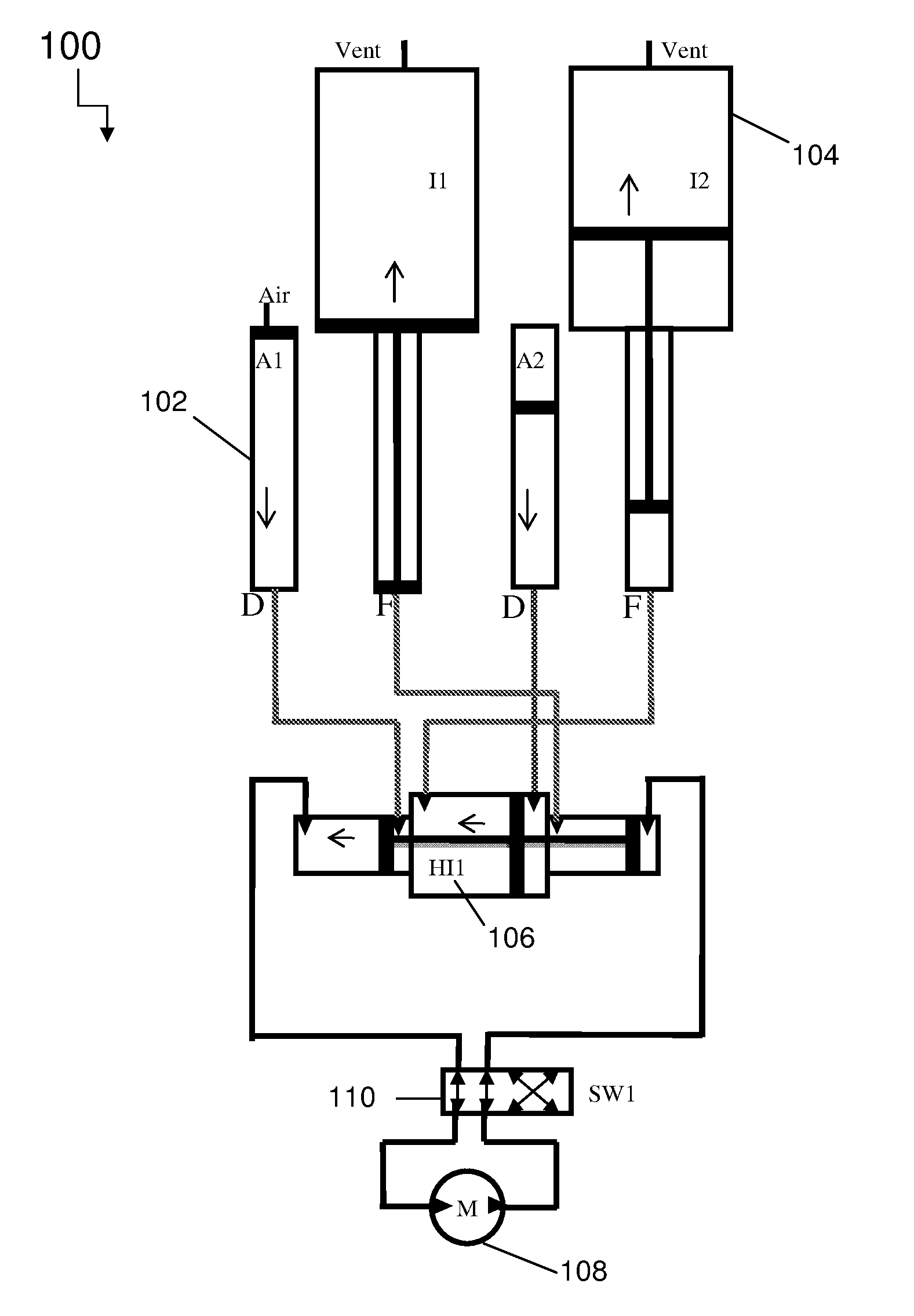
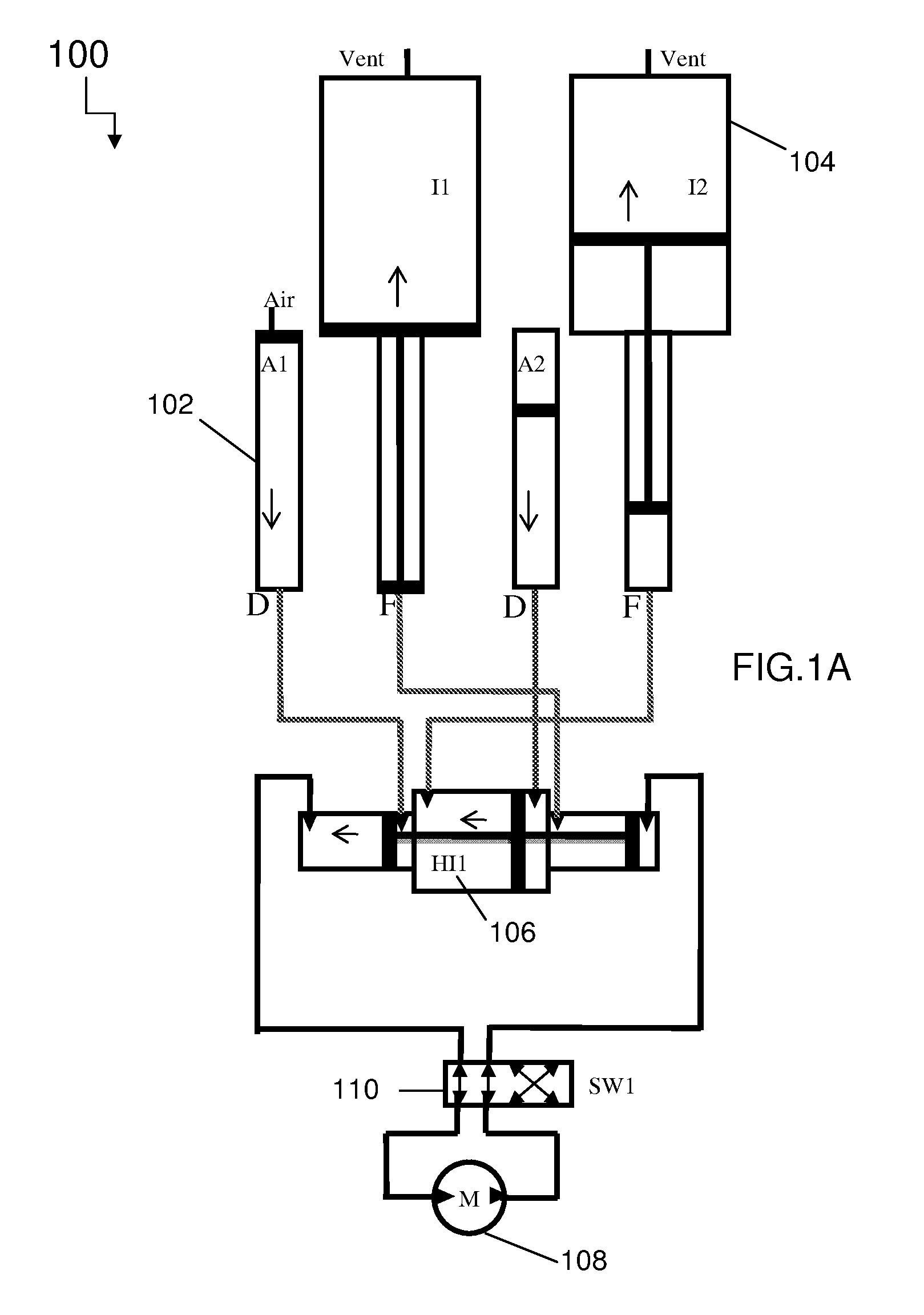
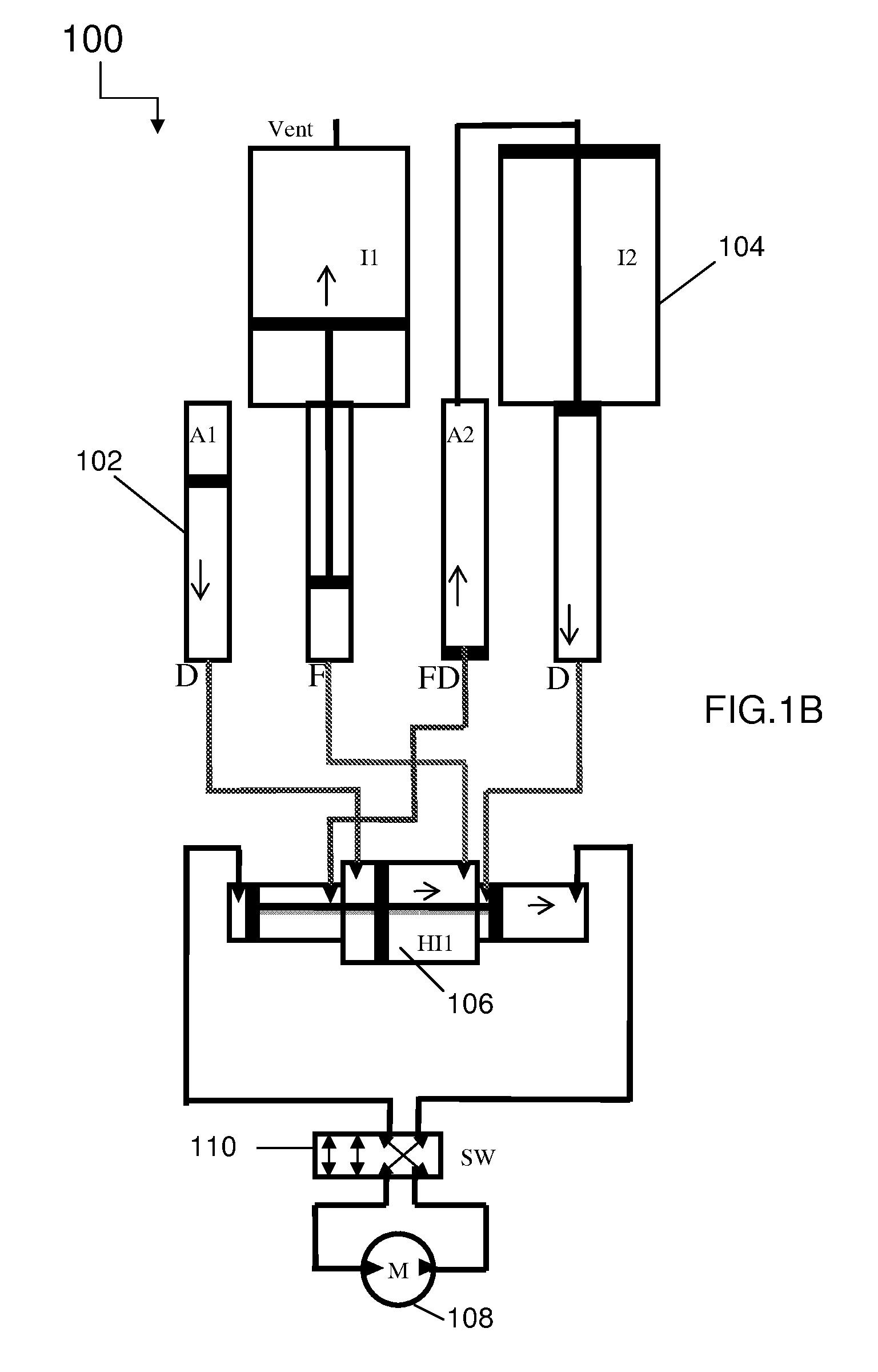
[0072]The various systems and methods described herein refer to multiple arrangements of pneumatic and hydraulic-pneumatic components, the components generally designated as follows: accumulators (A1, A2, . . . ); intensifiers (I1, I2, . . . ); hydraulic-hydraulic intensifiers (HI1; hydraulic motors (M), and directional valves (SW1, SW2, . . . ).

[0073]FIGS. 1A-1D depict the major pneumatic and hydraulic components for a compressed air energy storage and recovery system 100 using staged hydraulic conversion. FIGS. 1A-1D illustrate four time steps in a single full cycle. The system 100 includes two pneumatic-hydraulic accumulators 102 and two pneumatic-hydraulic intensifiers 104 paired with one double-acting hydraulic-hydraulic intensifier 106, coupled with a variable displacement hydraulic pump / motor 108. In particular, the system 100 includes two equally sized hydraulic-pneumatic accumulators 102, labeled A1 and A2, two hydraulic-pneumatic intensifiers 104, labeled I1 and I2, with h...


PUM


Abstract

The invention relates to power generation and energy storage and recovery. In particular, the invention relates to compressed gas energy storage and recovery systems using staged pneumatic conversion systems for providing narrow pressure ranges to a hydraulic motor.

Description

CROSS-REFERENCE TO RELATED APPLICATIONS[0001]This application claims priority to U.S. Provisional Patent Application Ser. Nos. 61 / 184,191, filed on Jun. 4, 2009; 61 / 222,286, filed on Jul. 1, 2009; 61 / 242,526, filed on Sep. 15, 2009; and 61 / 256,484, filed on Oct. 30, 2009, the disclosures of which are hereby incorporated herein by reference in their entireties.STATEMENT REGARDING FEDERALLY SPONSORED RESEARCH[0002]This invention was made with government support under IIP-0810590 and IIP-0923633 awarded by the NSF. The government has certain rights in the invention.FIELD OF THE INVENTION[0003]The invention relates to power generation and energy storage and recovery. More particularly, the invention relates to improving drivetrain efficiency in compressed gas energy storage and recovery systems.BACKGROUND OF THE INVENTION[0004]Storing energy in the form of compressed gas has a long history and components tend to be well tested and reliable and to have long lifetimes. The general princip...

Claims


Application Information

Patent Timeline
Patent Type & Authority Applications(United States)
IPC IPC(8): F16D31/02
CPCY02E60/15H02J15/006H02J2310/40Y02E60/16
Inventor BOLLINGER, BENJAMIN R.MCBRIDE, TROY O.
Owner SUSTAINX
Why Eureka
Try Eureka