Separation method and apparatus

a separation method and air technology, applied in lighting and heating apparatus, solidification, refrigeration and liquid storage, etc., can solve problems such as on-going operational costs, achieve the effects of reducing the amount of nitrogen vapor, increasing the capacity of the lower pressure column, and improving purity

Inactive Publication Date: 2011-06-16
PRAXAIR TECH INC
View PDF12 Cites 15 Cited by
  • Summary
  • Abstract
  • Description
  • Claims
  • Application Information

AI Technical Summary

Benefits of technology

[0015]The oxygen containing stream produced in the auxiliary column will have a lower nitrogen content than the exhaust stream that will have the effect of reducing the amount of nitrogen vapor within the lower pressure column to in turn increase the capacity of the lower pressure column and therefore, the entire cryogenic rectification process. Additionally, since the exhaust stream is being introduced into a bottom region of the auxiliary column, the auxiliary column is not being reboiled with nitrogen-rich vapor produced in the higher pressure column. This allows the lower pressure column to produce the oxygen at a higher purity than in the prior art discussed above if such high purity product is desired. Furthermore, the auxiliary column, as in the prior art, allows the lower pressure column to be operated at a lower pressure to save energy costs in the main compression of the incoming air to be separated. A major advantage of the method of the present invention is that additionally, since the exhaust stream pressure will set the pressure of the auxiliary column, the pressure of the auxiliary column nitrogen-rich vapor stream can also be set to a level that will allow such stream to be introduced into the pre-purification unit without further compression. This saves on the electrical power that would otherwise be consumed in such compression and therefore, the ongoing operational costs of running the process and plant incorporating the process as well as a compressor that is normally used for such purposes. In this regard, the ability to set the pressure of the lower pressure column also allows the pressure of the auxiliary column nitrogen-rich vapor stream to be set at a level that when taken in connection with losses of piping and heat exchangers and possibly control valves leading to the pre-purification unit will be optimal and not so high as to require expansion valves or the like for pressure let down purposes.
[0016]The cryogenic rectification process generates at least one impure oxygen stream containing oxygen and nitrogen and having an oxygen content no less than that of the air. This at least one impure oxygen stream, along with the exhaust stream, can be introduced into a bottom region of an auxiliary column and rectified along with the exhaust stream within the auxiliary column to form the oxygen containing liquid as a column bottoms and the auxiliary column nitrogen-rich vapor column overhead. The at least one oxygen containing stream that is withdrawn from the auxiliary column has a lower nitrogen content of that of the at least one impure oxygen stream and the exhaust stream and is introduced into the lower pressure column of the at least one air separation unit. The at least one impure oxygen stream can be composed of a crude liquid oxygen column bottoms produced in the higher pressure column. The use of the impure oxygen stream will act to reduce nitrogen within the lower pressure column to a level below that of the exhaust stream alone and will also allow for more auxiliary column nitrogen-rich vapor to be generated. If the exhaust stream were used alone, then the pre-purification unit would operate on the basis of a temperature swing adsorption cycle.

Problems solved by technology

This saves on the electrical power that would otherwise be consumed in such compression and therefore, the ongoing operational costs of running the process and plant incorporating the process as well as a compressor that is normally used for such purposes.

Method used


Image

  • Separation method and apparatus
  • Separation method and apparatus

Examples


Embodiment Construction

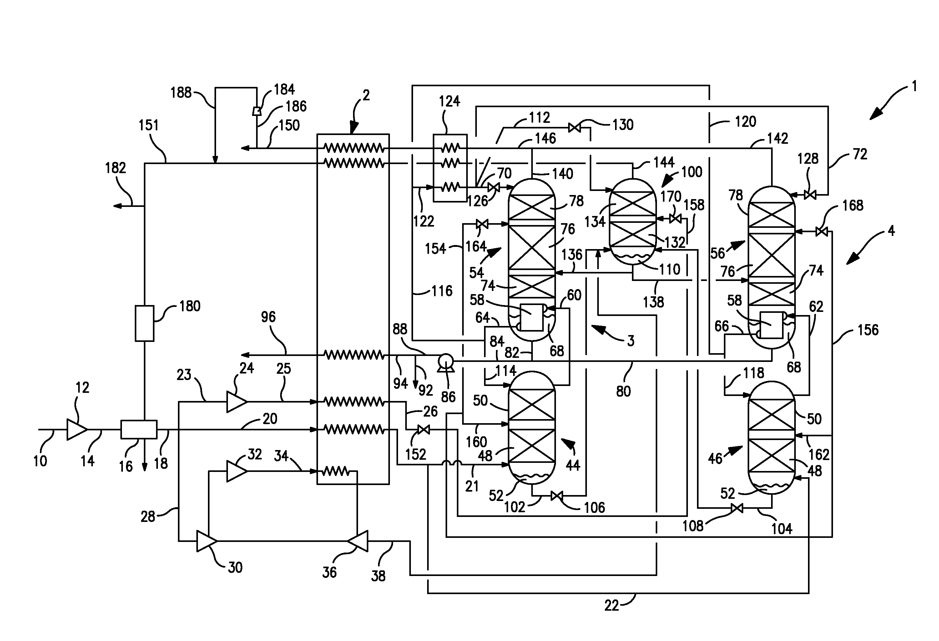
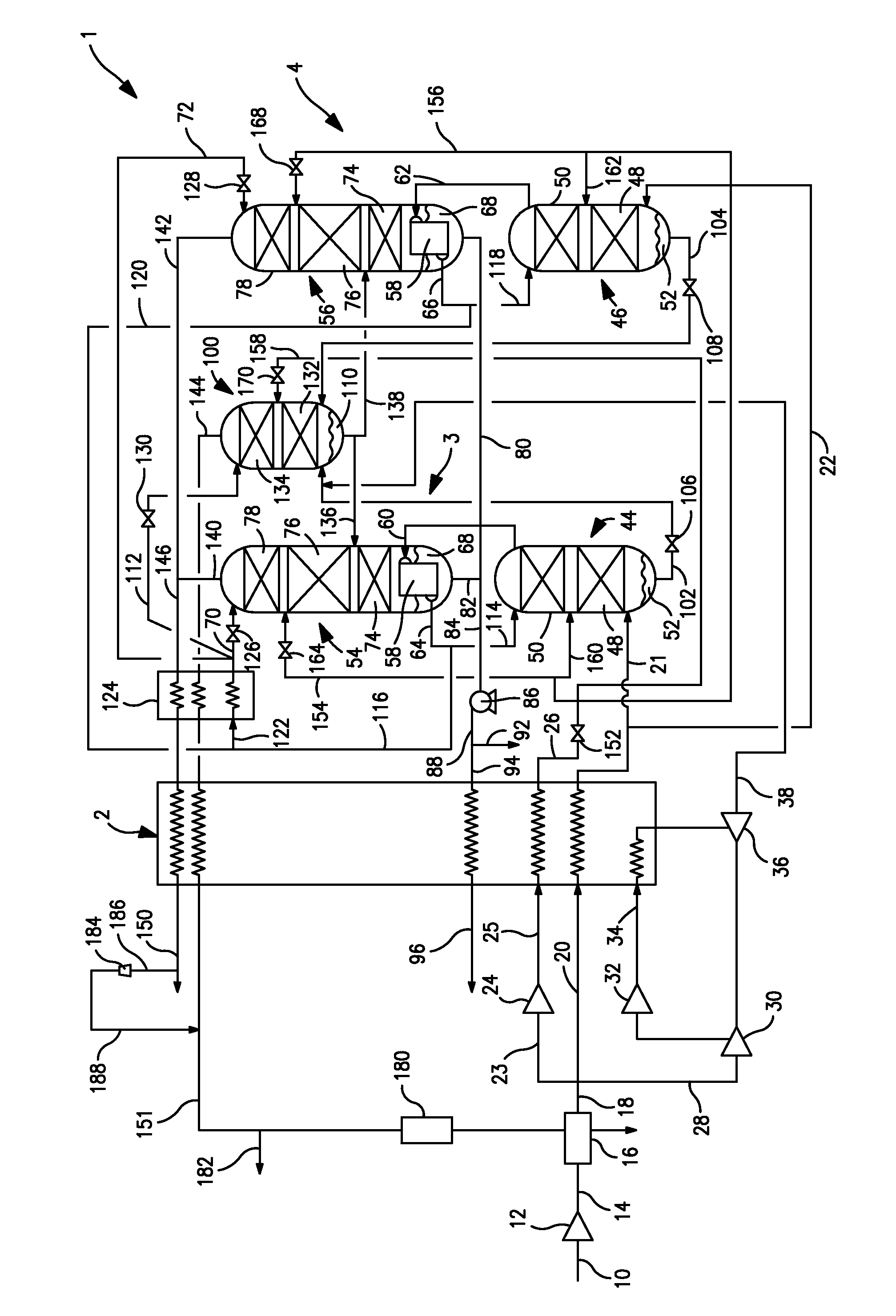
[0027]With reference to the FIGURE, a cryogenic rectification installation 1 is illustrated that is designed to separate air and thereby to produce an oxygen product. Cryogenic rectification installation 1 is provided with a main heat exchanger 2 to cool the air to a temperature suitable for its rectification within air separation units 3 and 4 and thereby produce an oxygen product that is discharged from the main heat exchanger 2 as an oxygen product stream 96 and a nitrogen product stream 150, to be discussed in more detail hereinafter. It is understood that air separation unit 4 as well as other possible air separation units that would be operatively associated with an auxiliary column 100, also to be discussed in more detail hereinafter, are optional in that the present invention could be practiced with a single air separation unit 3.

[0028]The air to be separated is introduced into apparatus 1 as an air stream 10 that is compressed in a main compressor 12 to produce a main compr...


PUM


Abstract

A method and apparatus for producing an oxygen product in which air is separated in an installation including one or more air separation units having higher and lower pressure columns. An exhaust stream produced from a turboexpander and optionally an impure oxygen stream such as that derivable from higher pressure column bottoms is rectified within an auxiliary column to produce an oxygen containing stream that is introduced into the lower pressure column of each of the air separation units to increase the capacity of such columns. The pressure within the auxiliary column is set by the pressure of the exhaust stream such that a nitrogen-rich vapor stream extracted from the top of the auxiliary column can be used in regenerating adsorbent within a pre-purification unit utilized in connection with the installation.

Description

RELATED APPLICATIONS[0001]This application is a continuation-in-part of U.S. patent application Ser. No. 12 / 634,810, filed Dec. 10, 2009.FIELD OF THE INVENTION[0002]The present invention relates to a method and apparatus for separating air into oxygen and nitrogen-rich fractions. More particularly, the present invention relates to such a method and apparatus in which one or more air separation units having higher and lower pressure columns are connected to an auxiliary column that produces one or more oxygen containing streams that are lean in nitrogen and that are introduced into lower pressure columns to allow the air separation units to operate at a higher capacity and a nitrogen-rich vapor stream that can be used in regenerating adsorbent beds of a pre-purification unit used in purifying the air without further compression.BACKGROUND OF THE INVENTION[0003]Large quantities of high purity oxygen are required for purposes of coal gasification where the resulting synthesis gas will ...

Claims


Application Information

Patent Timeline
Patent Type & Authority Applications(United States)
IPC IPC(8): F25J3/02
CPCF25J3/04963F25J2205/64F25J3/04206F25J3/04448F25J2230/42F25J3/0429F25J3/04181F25J3/04084F25J3/04872F25J3/04824F25J2235/50F25J3/0409F25J3/04969F25J3/04236F25J2245/42F25J3/04951F25J2205/30
Inventor HOWARD, HENRY EDWARDJAIN, SEMANT
Owner PRAXAIR TECH INC
Why Eureka
Try Eureka