Cooled egr system for coolant heating during cold engine start

a technology of coolant heating and engine start, which is applied in the direction of electrical control, process and machine control, etc., can solve the problems of reducing reducing the fuel economy, and losing heat, so as to reduce the thermal efficiency of the engine, reduce the heat loss, and increase the viscosity of the engine fluid.

Active Publication Date: 2011-06-16
FORD GLOBAL TECH LLC
View PDF10 Cites 46 Cited by
  • Summary
  • Abstract
  • Description
  • Claims
  • Application Information

AI Technical Summary

Benefits of technology

[0002]Under cold start conditions, an engine has cooled to ambient conditions, which may be relatively hot or cold, and each component of the engine warms-up to a desired operating temperature. During this time, there may be high friction within the engine due to a higher viscosity of engine fluids such as engine oil when they are relatively cold, and further, heat may be lost to engine coolant thereby reducing a thermal efficiency of the engine. Overall, these effects may lead to a lower fuel economy, for example.
[0004]By using HP-EGR to heat the coolant, fuel economy may be improved without adding additional components to the engine system for coolant heating. Further, engine coolant temperature may be increased at a high rate due to the relatively low temperature of the engine coolant compared to the exhaust gas temperature leading to improved fuel economy during the cold start. Moreover, increasing an amount of HP-EGR before the engine is warmed-up may reduce combustion stability; therefore, by adjusting one or more engine operating parameters such as cam timing and fuel injection, combustion stability may be maintained.

Problems solved by technology

During this time, there may be high friction within the engine due to a higher viscosity of engine fluids such as engine oil when they are relatively cold, and further, heat may be lost to engine coolant thereby reducing a thermal efficiency of the engine.
Overall, these effects may lead to a lower fuel economy, for example.
Moreover, increasing an amount of HP-EGR before the engine is warmed-up may reduce combustion stability; therefore, by adjusting one or more engine operating parameters such as cam timing and fuel injection, combustion stability may be maintained.

Method used


Image

  • Cooled egr system for coolant heating during cold engine start
  • Cooled egr system for coolant heating during cold engine start
  • Cooled egr system for coolant heating during cold engine start

Examples


Embodiment Construction

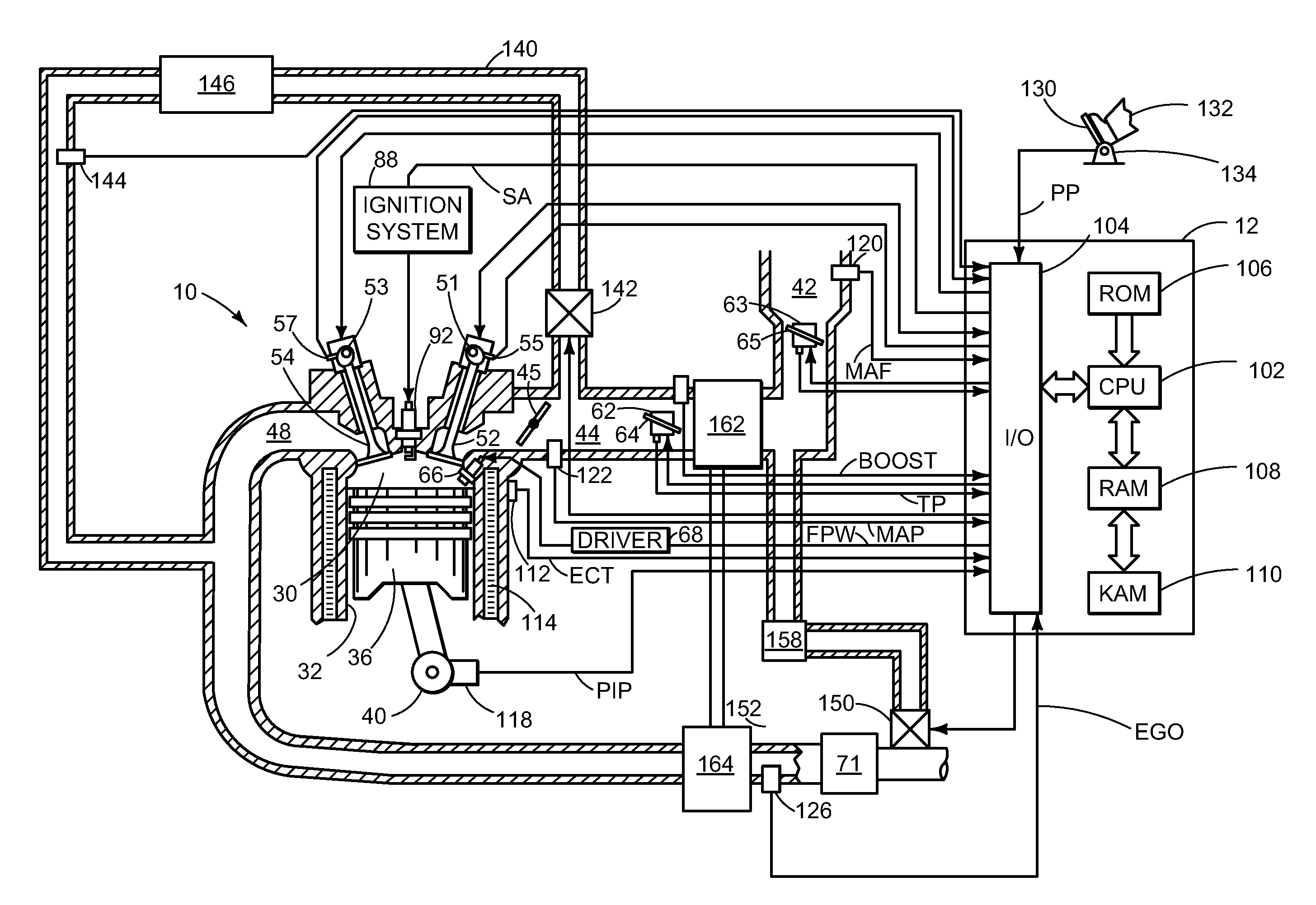
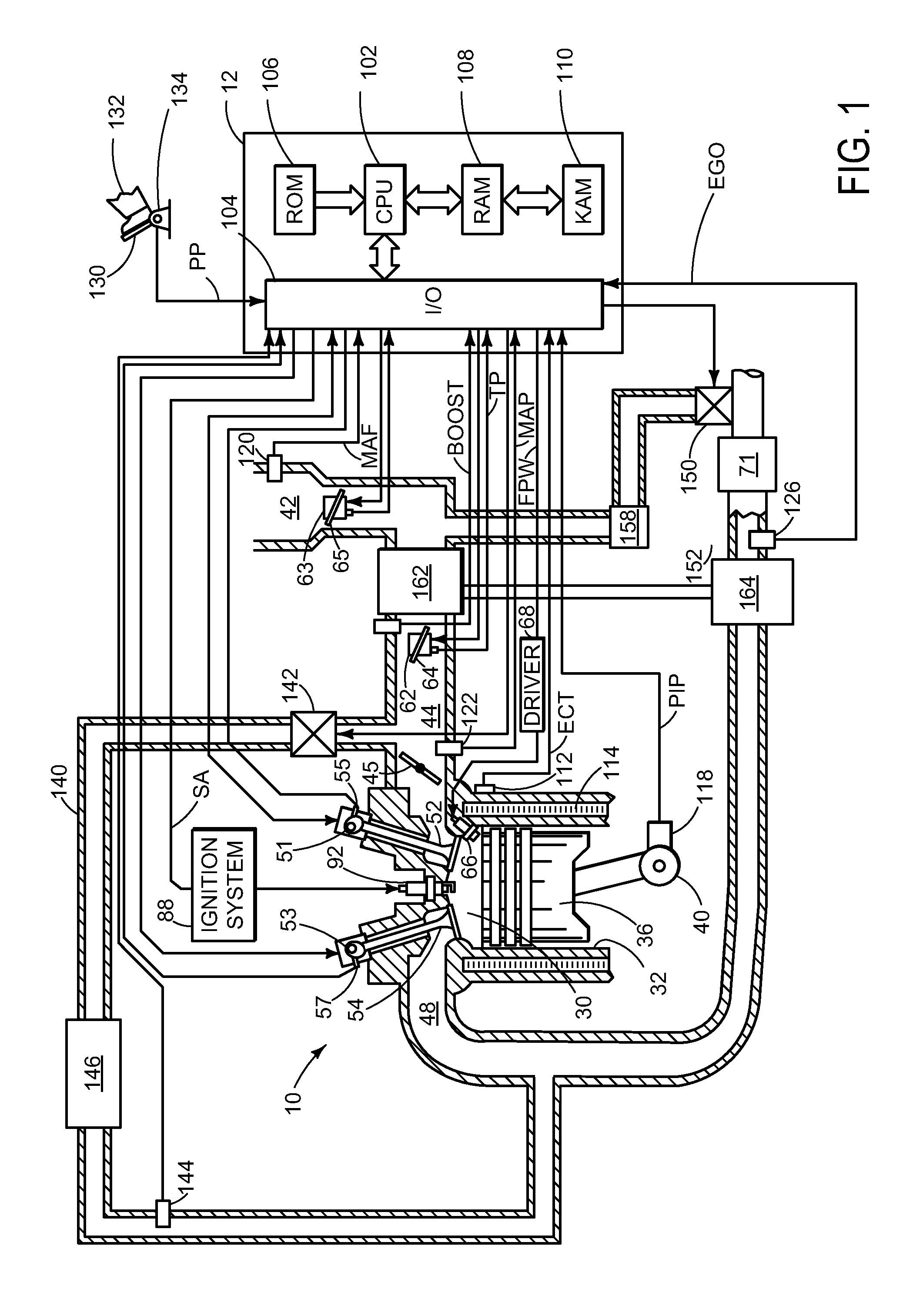
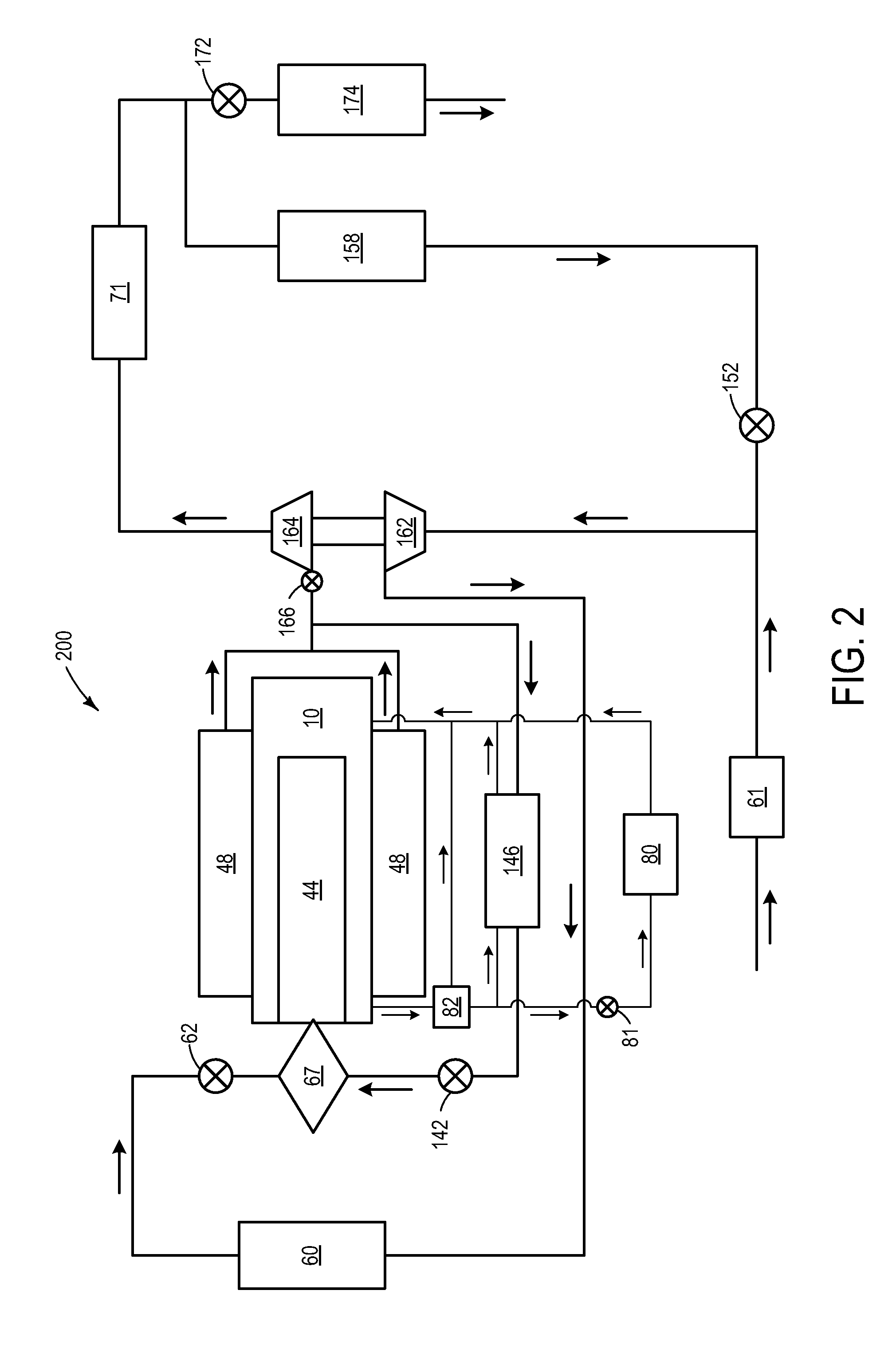
[0012]The following description relates to systems and methods for using exhaust gas recirculation (EGR) to heat an engine in a vehicle during a cold start. In one example, after light-off of an exhaust catalyst when all of the exhaust gas is no longer needed to heat the exhaust catalyst, a high-pressure exhaust gas recirculation (HP-EGR) system is operated in order to transfer heat to engine coolant via an HP-EGR cooler. By routing some of the exhaust gas through the HP-EGR system, heat exchange can occur between the high temperature exhaust gas and the relatively low temperature engine coolant. Further, one or more engine operating parameters (e.g., cam timing, fuel injection, etc.) may be adjusted in order to maintain combustion stability while a high amount of EGR enters the combustion chamber during the cold start. As such, engine heating may be expedited while thermal efficiency of the engine may be improved without reducing combustion stability.

[0013]Referring now to FIG. 1, ...


PUM


Abstract

Various systems and method for heating an engine in a vehicle during a cold start are described. In one example, thermal efficiency of the engine is improved by heating engine coolant via a high-pressure exhaust gas recirculation (HP-EGR) system. For example, after light-off of an exhaust catalyst, exhaust gas is routed through the HP-EGR system which includes a HP-EGR cooler. Heat from the exhaust gas is then used to warm the engine coolant via the HP-EGR cooler. One or more engine operating parameters are adjusted in response to the HP-EGR entering the engine during the cold start in order to maintain combustion stability.

Description

TECHNICAL FIELD[0001]The present application relates to heating an engine during a cold start and, more specifically, to using an exhaust gas recirculation cooler to heat engine coolant.BACKGROUND AND SUMMARY[0002]Under cold start conditions, an engine has cooled to ambient conditions, which may be relatively hot or cold, and each component of the engine warms-up to a desired operating temperature. During this time, there may be high friction within the engine due to a higher viscosity of engine fluids such as engine oil when they are relatively cold, and further, heat may be lost to engine coolant thereby reducing a thermal efficiency of the engine. Overall, these effects may lead to a lower fuel economy, for example.[0003]The inventors herein have recognized the above problems and have devised an approach to at least partially address them. Thus, a method for heating a turbocharged engine in a vehicle is disclosed. The method comprises, during a cold engine start and after light-o...

Claims


Application Information

Patent Timeline
Patent Type & Authority Applications(United States)
IPC IPC(8): F02M25/07
CPCF01P2037/02Y02T10/47F02D41/0055F02D41/0065F02D41/064F02D2200/021F02D2200/0802F02M25/0707F02M25/0709F02M25/0731F02M25/0732F02M25/0738F02M25/0744F02M25/0754F01P2060/02F02M26/05F02M26/06F02M26/28F02M26/24F02M26/33F02M26/38F02M26/47Y02T10/40
Inventor SURNILLA, GOPICHANDRABIDNER, DAVID KARLSTYLES, DANIEL JOSEPH
Owner FORD GLOBAL TECH LLC
Why Eureka
Try Eureka