Thermally-Assisted Magnetic Recording Head

a technology of magnetic recording head and magnetic recording head, which is applied in the field of magnetic recording head thermally assisted, can solve the problems of difficult to increase coercive force, reduce distance, and thermal instability of grains, and achieves the effects of ensuring good floating characteristic, minimizing slider warping, and high efficiency

Inactive Publication Date: 2011-06-16
HITACHI LTD
View PDF3 Cites 20 Cited by
  • Summary
  • Abstract
  • Description
  • Claims
  • Application Information

AI Technical Summary

Problems solved by technology

The magnetic recording medium has a problem of heat fluctuation in which as the crystal grains are miniaturized in diameter, the grains become thermally unstable.
However, since there is a limit to the property of a magnetic material used in the recording head and to the reduction in the distance between the magnetic disk and the head, it is difficult to increase the coercive force as the recording density is enhanced.
This makes it possible to easily record a medium even with a high coercive force which it has been difficult for the conventional magnetic head to record because of an insufficient recording magnetic field strength.
Major causes for the light intensity attenuation include absorption loss and scattering loss that occur as the beam passes through the optical parts, and a connection loss resulting from deviations of optical parts from their ideal positions when they are bonded together.
However, as the miniaturization and the floating distance reduction make a progress, a warping of the slider itself poses a problem.

Method used


Image

  • Thermally-Assisted Magnetic Recording Head
  • Thermally-Assisted Magnetic Recording Head
  • Thermally-Assisted Magnetic Recording Head

Examples


embodiment 1

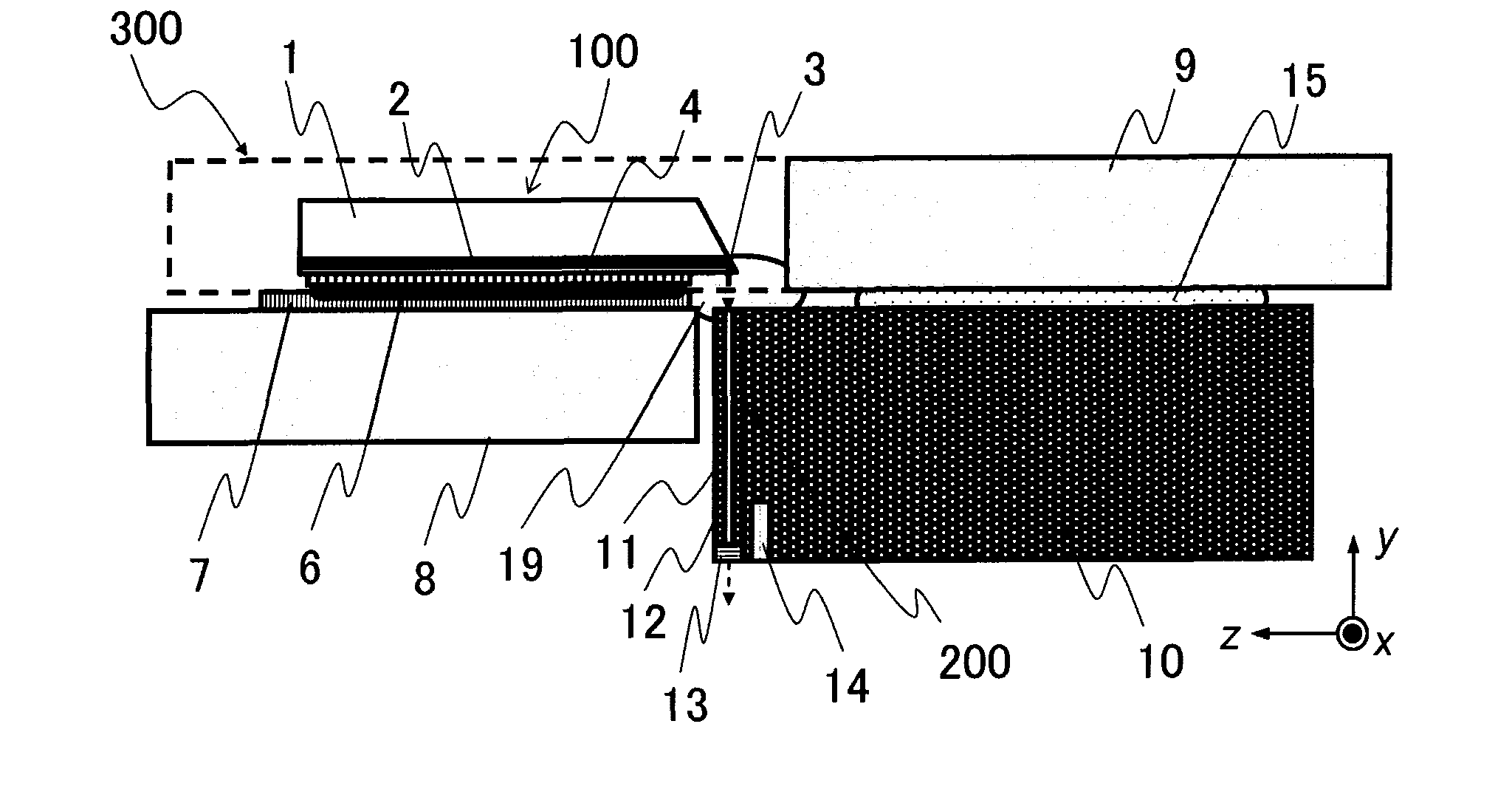
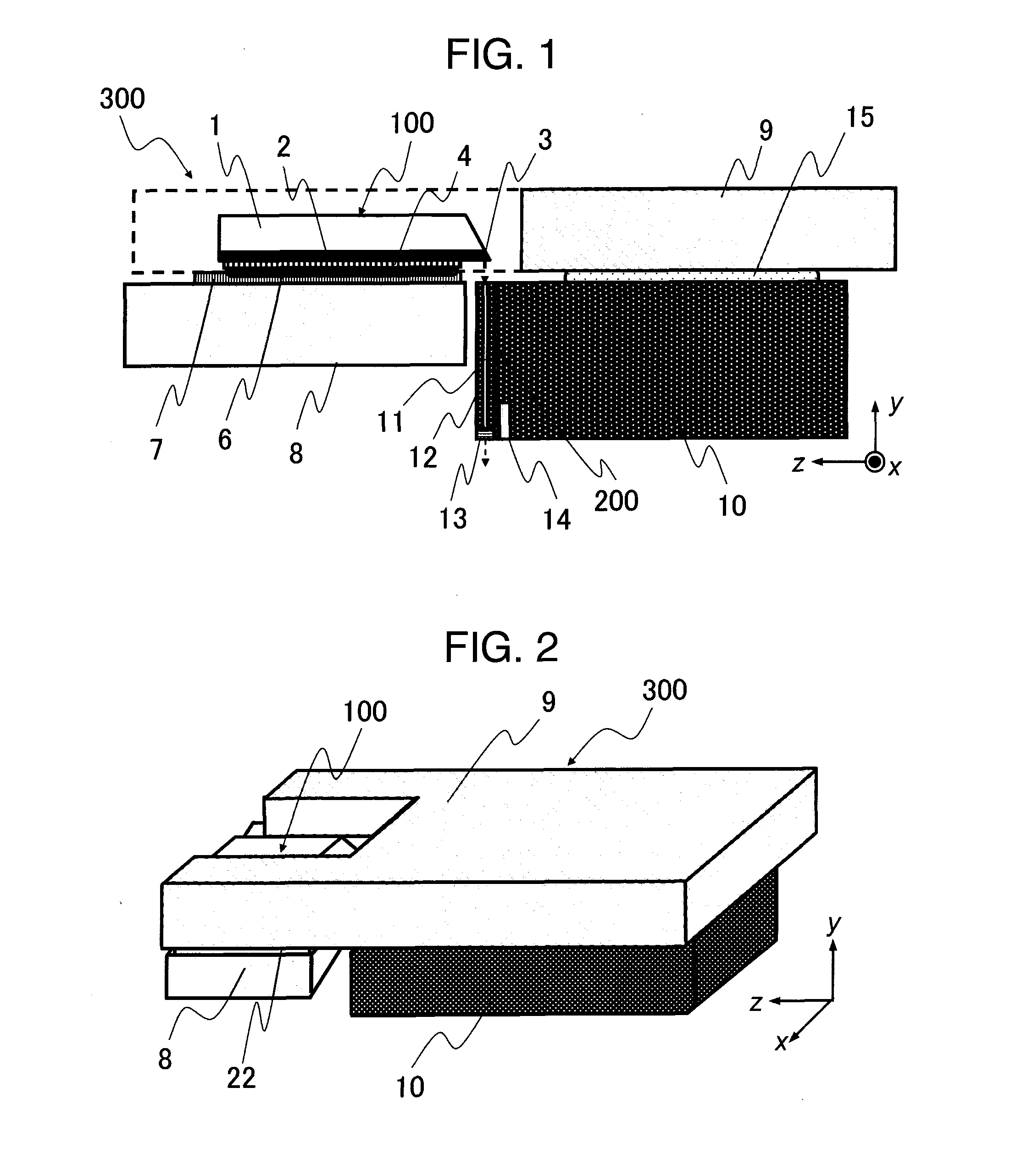
[0061]FIG. 1 is a cross-sectional view of a thermally assisted magnetic recording head 300 of this embodiment cut along a rotation circumferential direction of a recording medium (magnetic disk) not shown. FIG. 2 is a perspective view of the thermally assisted magnetic recording head 300 shown in FIG. 1. In FIG. 1, FIG. 2 and other figures, a Cartesian coordinate system is shown for the understanding of a positional relation of the thermally assisted magnetic recording head 300 (or its part, e.g., slider 10) among these figures. In either of these figures, a z-axis represents the direction in which the recording medium advances relative to the magnetic head (direction of movement) and a y-axis represents the direction in which the magnetic head is secured to the slider. The direction of advance of the recording medium in the hard disk drive is also referred to as a rotational direction of the magnetic disk (a circumferential direction of the magnetic disk at rest). The slider 10 is ...

embodiment 2

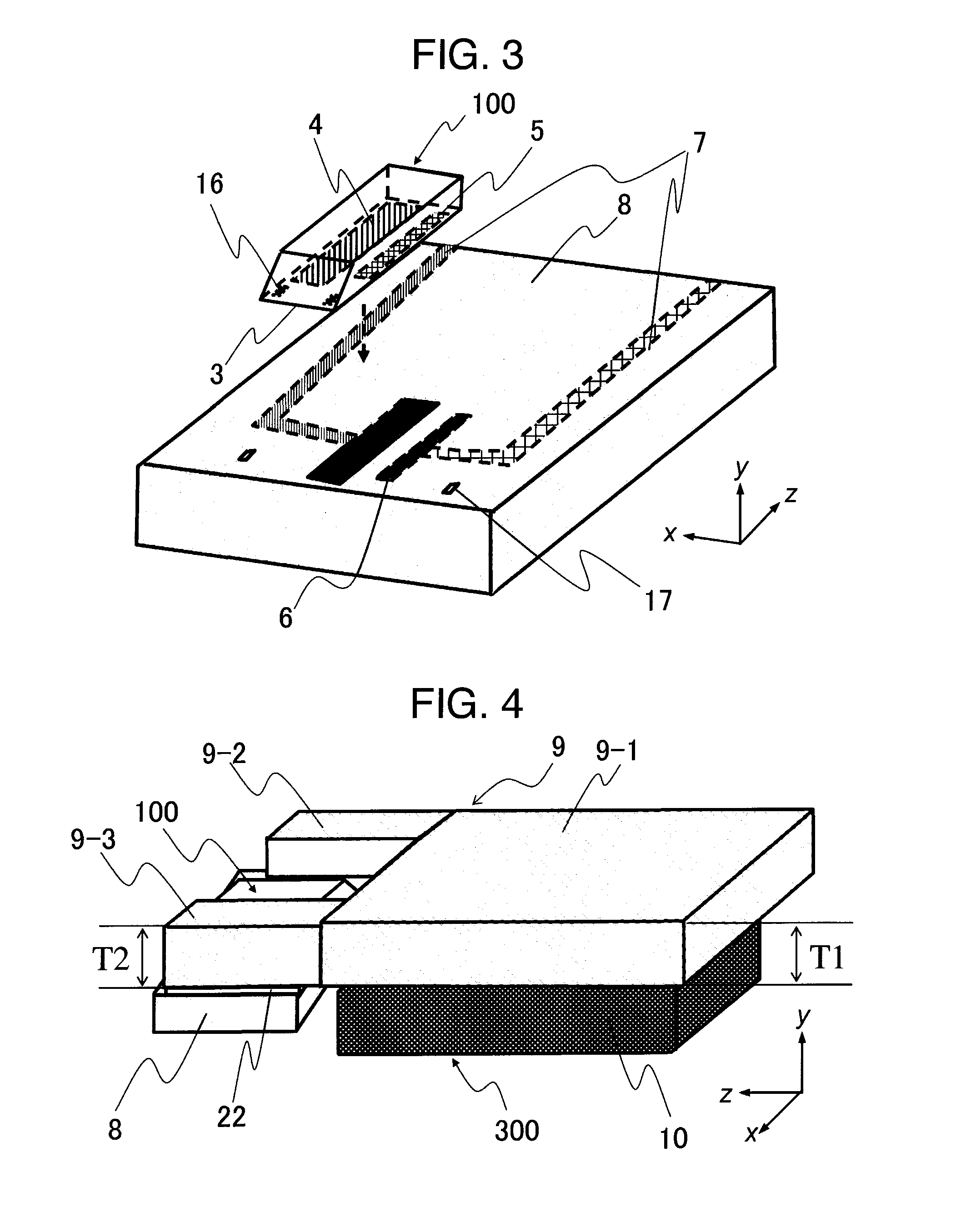
[0080]FIG. 4 is a perspective view of another embodiment of this invention, schematically showing a magnetic head 300 that, instead of the so-called recessed type second submount 9 shown in embodiment 1, uses a second submount 9 composed of three flat (platelike) submounts 9-1, 9-2, 9-3 assembled into a recessed structure. In this embodiment that does not form the second submount 9 as one integral structure, there is an advantage that the manufacturing process of the second submount 9 does not require a special fabrication. In this structure, consideration needs to be taken of thickness tolerances of the submounts 9-1, 9-2, 9-3 and the thickness T1 of the submount 9-1 is preferably made larger than that T2 of the other submounts 9-2, 9-3. Since these submounts 9-1, 9-2, 9-3 are each formed with wiring, it is necessary to use a soldering material or a conductive adhesive in connecting the submount 9-1 with the submounts 9-2, 9-3.

embodiment 3

[0081]FIG. 5 is a perspective view of a magnetic head 300 of still another embodiment of this invention. In this embodiment, although the integrally formed second submount 9 is used as with embodiment 1, its width (in the x-axis direction) L1 is set wider than the width L2 of the slider 10. Between the edges of the undersurface of the second submount 9 (two sides extending in the z-axis direction) and the sides of the slider 10 (y-z plane) is applied a third bonding agent (heat dissipating material) 18 with high heat conductivity.

[0082]In a hard disk drive, as the magnetic disk rotates, the slider 10 floats because of an air stream produced by the rotation. This results in the slider 10 being easily cooled depending on the velocity of the air stream. On the other hand, the adhesive with very high heat conductivity of around 20 W / mK is often mixed with metal particles such as silver, exhibiting a characteristic property of high elastic modulus or hardness. With such an adhesive havin...


PUM

PropertyMeasurementUnit
refractive indexaaaaaaaaaa
floating distanceaaaaaaaaaa
lengthaaaaaaaaaa

Abstract

In a thermally assisted magnetic recording head having a light source and a waveguide to lead a laser beam radiated from the light source to a front end of the magnetic head, while blocking an adverse effect of heat generated in the light source and securing a good floating characteristic, the light source and the magnetic head are optically coupled with high efficiency and the magnetic head itself is reduced in size. This invention provides a reflection mirror that is formed of a part or whole of one inclined end surface of the semiconductor laser mounted on the first submount. Near one end surface of the slider is provided the optical waveguide that pierces through the slider in a direction of the thickness thereof. The slider is mounted on the second submount and the positions of the first submount and the second submount are adjusted to practically align the light axis of the beam emitted from the mirror with the light axis of the optical waveguide, thereby realizing a novel thermally assisted magnetic recording head.

Description

INCORPORATION BY REFERENCE[0001]This application claims the priority benefit of Japanese Patent Application No. 2008-151223, filed on Jun. 10, 2008, the entire descriptions of which are incorporated herein by reference.TECHNICAL FIELD[0002]The present invention relates to a thermally assisted magnetic recording head comprising a magnetic recording medium, a means to write in the recording medium by a magnetic field and a means to heat the recording medium with a laser beam.BACKGROUND ART[0003]With the development of information society in recent years, voice and video have progressed in the level of resolution and the volume of data traffic in the Internet has also increased significantly. This in turn has resulted in an increase in electronic data volume accumulated in servers and the like, making it necessary to expand the capacity of information recording systems. Optical disc drives and hard disk drives installed as information recording devices in personal computers, recorders ...

Claims


Application Information

Patent Timeline
Patent Type & Authority Applications(United States)
IPC IPC(8): G11B13/08G11B13/04
CPCG11B5/314G11B5/4833G11B2005/0021G11B2005/0005G11B5/4866
Inventor ARAI, SATOSHIMATSUSHIMA, NAOKINANIWA, IRIZOSHIMIZU, JUNICHIRO
Owner HITACHI LTD
Why Eureka
Try Eureka