Device for compressing a compact toroidal plasma for use as a neutron source and fusion reactor

a technology of toroidal plasma and compact plasma, which is applied in the direction of nuclear reactors, greenhouse gas reduction, nuclear engineering, etc., can solve the problems of low efficiency of toroidal plasma compression and achieve good isolation

Inactive Publication Date: 2011-06-16
WOODRUFF SCI
View PDF4 Cites 64 Cited by
  • Summary
  • Abstract
  • Description
  • Claims
  • Application Information

AI Technical Summary

Benefits of technology

[0009]Particular aspects represent a fundamental departure from the prior art, and provide an adiabatic compression scheme for compact toroidal plasma that maintains stability and good isolation from the walls of the compression chamber throughout the compression cycle, thereby raising plasma temperature and density to levels useful for producing fusion power.

Problems solved by technology

Unfortunately, such tokamak compression suffers from low efficiency, because most of the energy of the ramped poloidal field is put into a vacuum field outside the plasma, not in the region of interest.

Method used


Image

  • Device for compressing a compact toroidal plasma for use as a neutron source and fusion reactor
  • Device for compressing a compact toroidal plasma for use as a neutron source and fusion reactor
  • Device for compressing a compact toroidal plasma for use as a neutron source and fusion reactor

Examples


Embodiment Construction

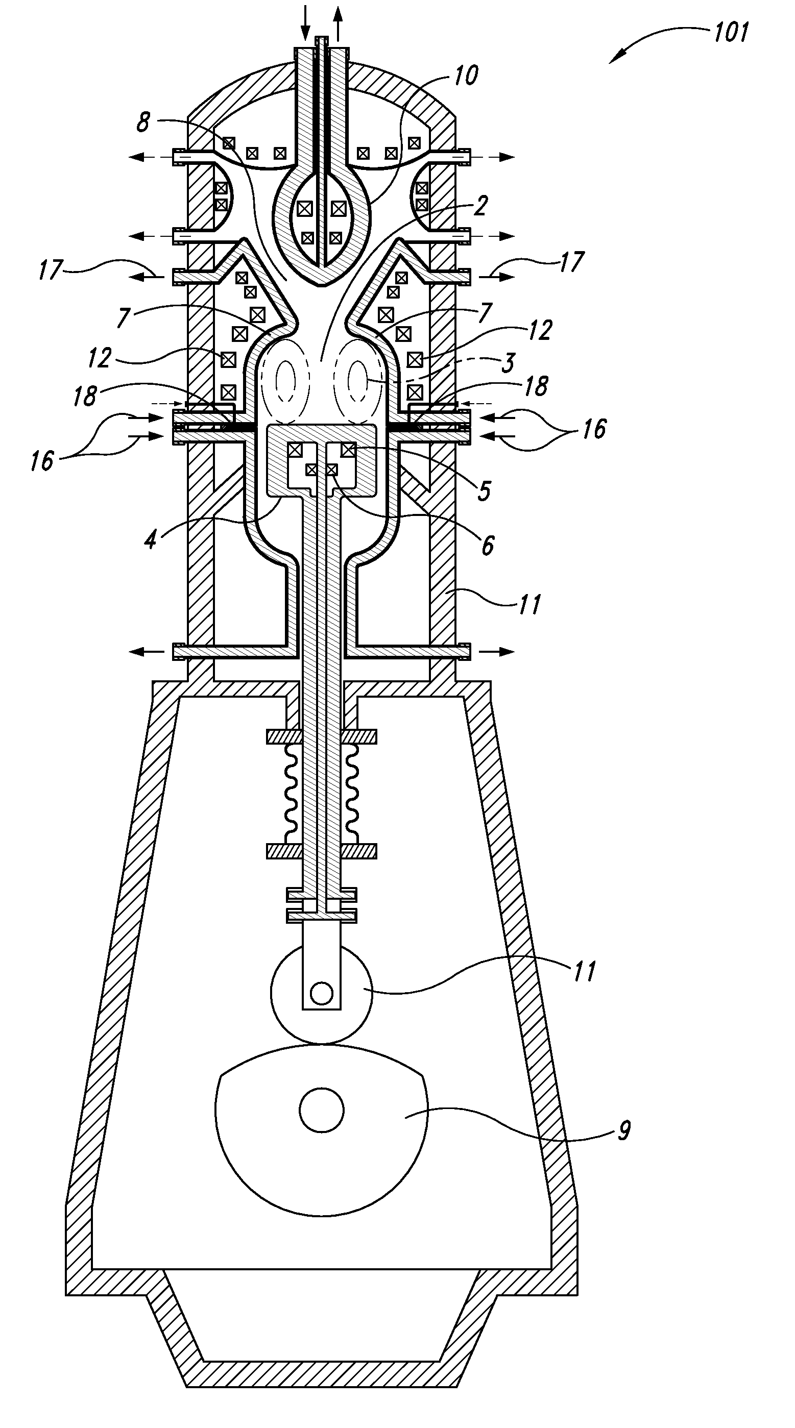
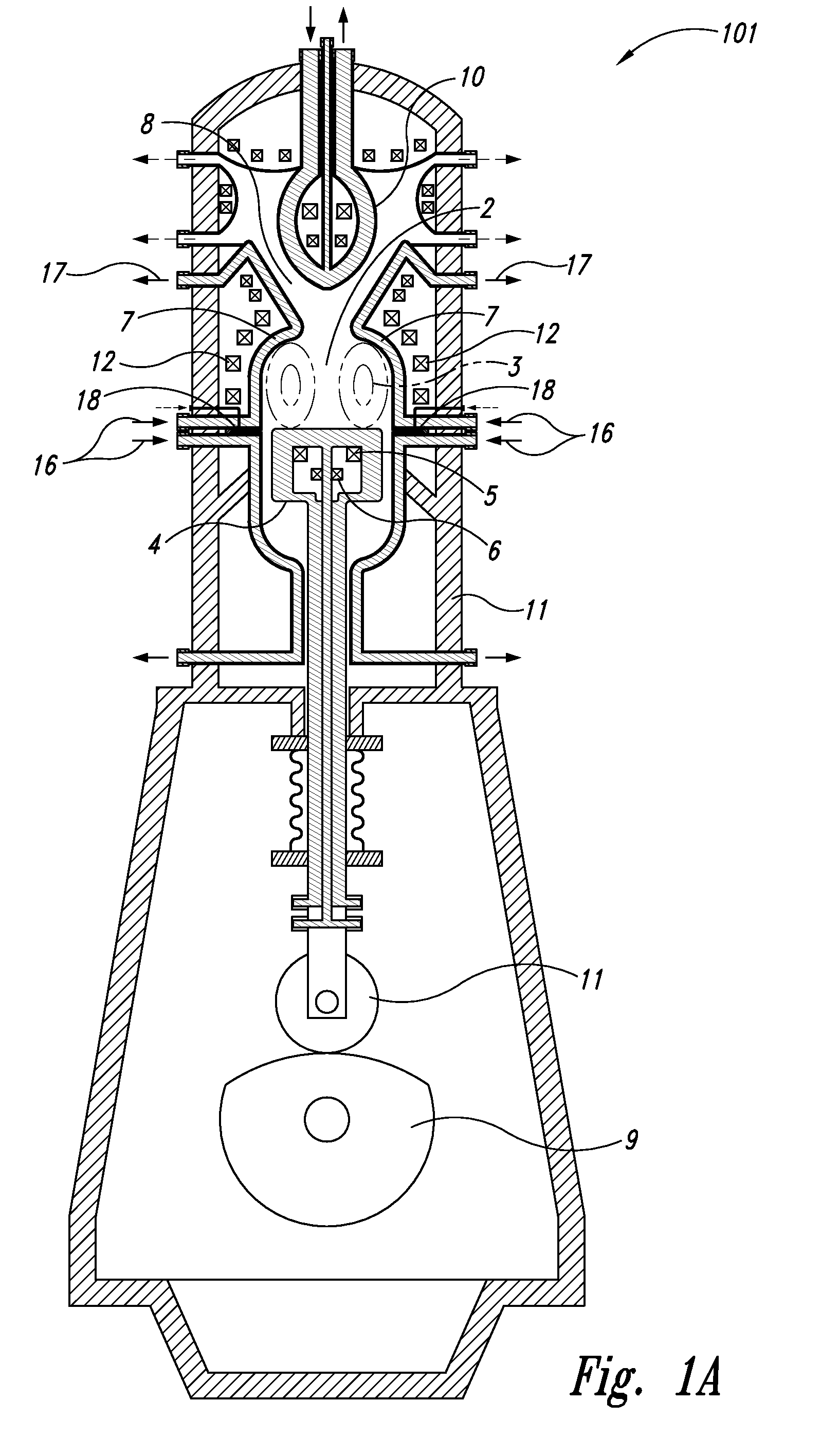
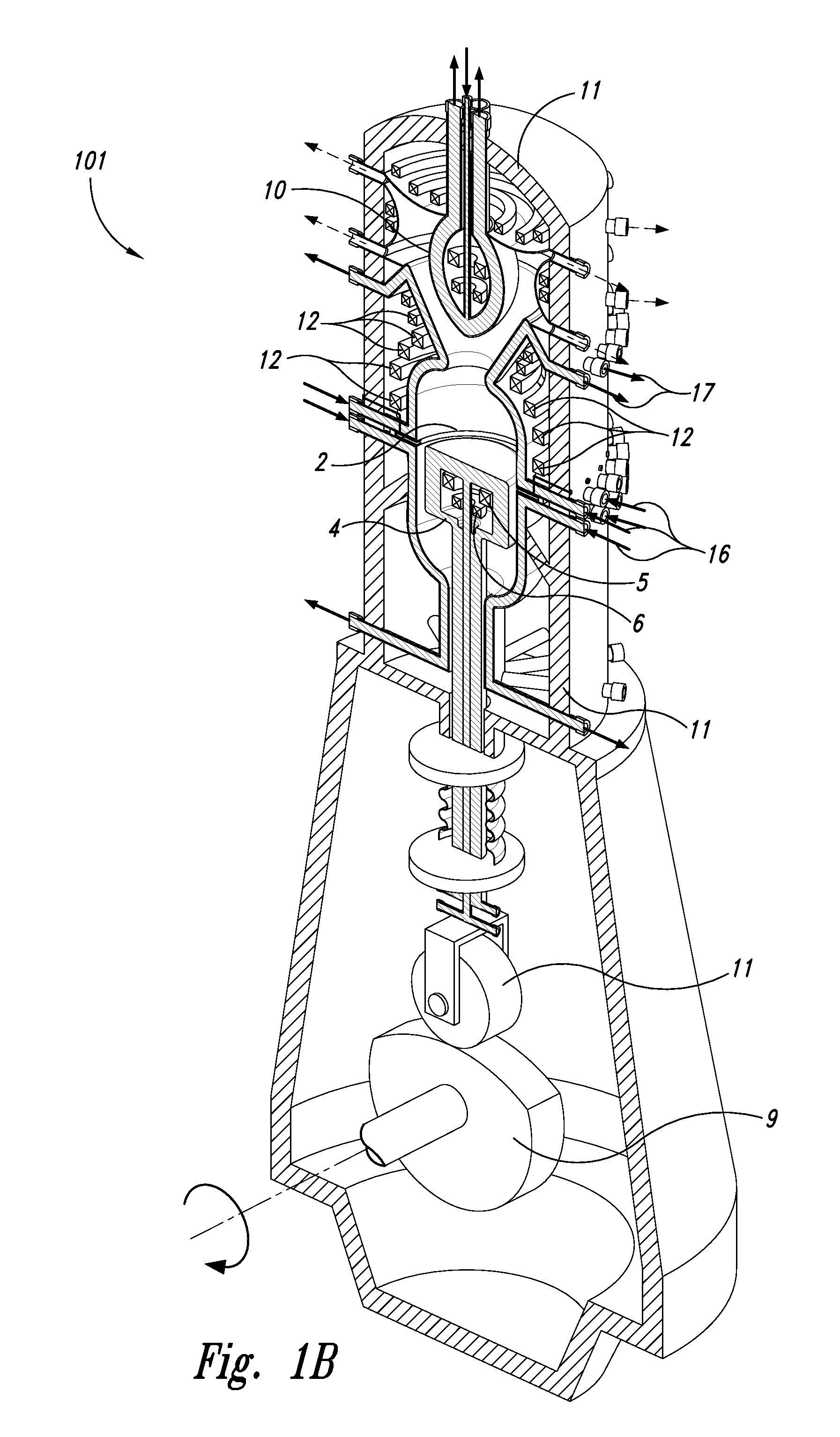
[0048]Overview. Provided are methods and devices for compression of a spheromak plasma (e.g., derived from at least one of neutronic fuels, aneutronic fuels, deuterium-trirtium (D-T), deuterium-deuterium (D-D), proton-boron-11 (p-B11), and deuterium-helium-3 (D-He3)) in a magnetic well configured within a plasma combustion chamber using an induction coil axially adjacent to the plasma, wherein a moveable member (e.g., piston, cam and follower) drives the induction coil toward the plasma, pushing the plasma via magnetic pressure into the magnetic well and compressing the plasma substantially adiabatically (e.g., coil motion is well below the plasma sound speed). The compression quickly increases both plasma density and temperature past the point of ignition, and after plasma burn, the coil is backed-off to allow the plasma to re-expand, providing for refueling and repetition of the compression cycle. Additionally provided are spaced annular plasma formation electrodes, suitably confi...


PUM


Abstract

Provided are methods and devices for compression of a spheromak plasma (e.g., deuterium-trirtium (D-T)-derived) in a magnetic well configured within a plasma combustion chamber using an induction coil axially adjacent to the plasma, wherein a moveable member (e.g., piston, cam and follower) drives the induction coil toward the plasma, pushing the plasma via magnetic pressure into the magnetic well and compressing the plasma substantially adiabatically (e.g., coil motion is well below the plasma sound speed). The compression quickly increases both plasma density and temperature past the point of ignition, and after plasma burn, the coil is backed-off to allow the plasma to re-expand, providing for refueling and repetition of the compression cycle. Additionally provided are spaced annular plasma formation electrodes, suitably configured for generating and injecting magnetized plasma into a plasma combustion chamber. Preferably, spaced annular plasma formation electrodes are used in combination with moveable compression members as disclosed herein.

Description

CROSS-REFERENCE TO RELATED APPLICATIONS[0001]This application claims the benefit of priority to U.S. Provisional Patent Application Ser. No. 61 / 287,170, filed Dec. 16, 2009 and entitled FUSION INTERNAL COMBUSTION ENGINE, which is incorporated by reference herein in its entirety.STATEMENT REGARDING FEDERALLY-SPONSORED RESEARCH[0002]The invention was made with government support under Contract No. DE-FG02-06ER84449 from the United States Department of Energy (DOE). The United States government has certain rights in the invention.FIELD OF THE INVENTION[0003]The present invention relates generally to the use of a magnetic coil contained in a moving member (e.g., piston) to adiabatically compress a magnetized plasma (e.g., containing deuterium and tritium fuel), to a point where plasma pressure is sufficient to achieve ignition thereof, and in more particular aspects, the compression drives the plasma temperature and density to fusion regimes, resulting in steady-state fusion power that ...

Claims


Application Information

Patent Timeline
Patent Type & Authority Applications(United States)
IPC IPC(8): G21B1/05
CPCG21B1/05Y02E30/12H05H3/06Y02E30/10
Inventor WOODRUFF, SIMON
Owner WOODRUFF SCI
Why Eureka
Try Eureka