Stud for stud welding

a technology for welding studs and studs, applied in the direction of screws, washing machines, ways, etc., can solve the problems of requiring relatively expensive rework, difficult welding of studs onto body sheets that are becoming increasingly thinner, and “burning” of body sheets

Active Publication Date: 2011-06-16
NEWFREY
View PDF12 Cites 4 Cited by
  • Summary
  • Abstract
  • Description
  • Claims
  • Application Information

AI Technical Summary

Benefits of technology

[0033]In the case of studs having a large flange diameter, it is advantageous to provide a locating point for automatic feeding into welding installations and for the assembly (screwing on or mounting attachments). Said locating point is provided on the shank end face opposite the head section and has a smaller diameter than the shank.

Problems solved by technology

The welding of studs onto body sheets that are becoming increasingly thinner turns out to be difficult.
This may lead to “burn-through” of the body sheet.
If a defect affecting the stud and / or the sheet occurs at this moment for certain reasons, relatively expensive rework is necessary.
For at this moment the sheet is already painted as a rule and the repair of the welding spot and the re-application of a stud consequently require complicated subsequent treatment of the surface of the body sheet.

Method used


Image

  • Stud for stud welding
  • Stud for stud welding

Examples


Embodiment Construction

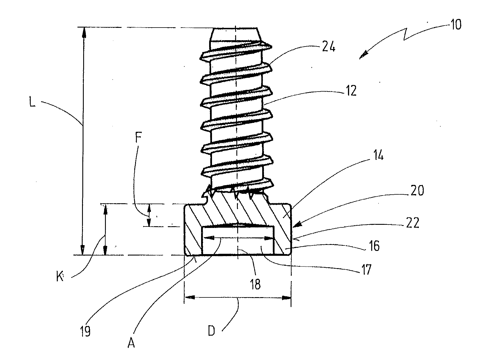
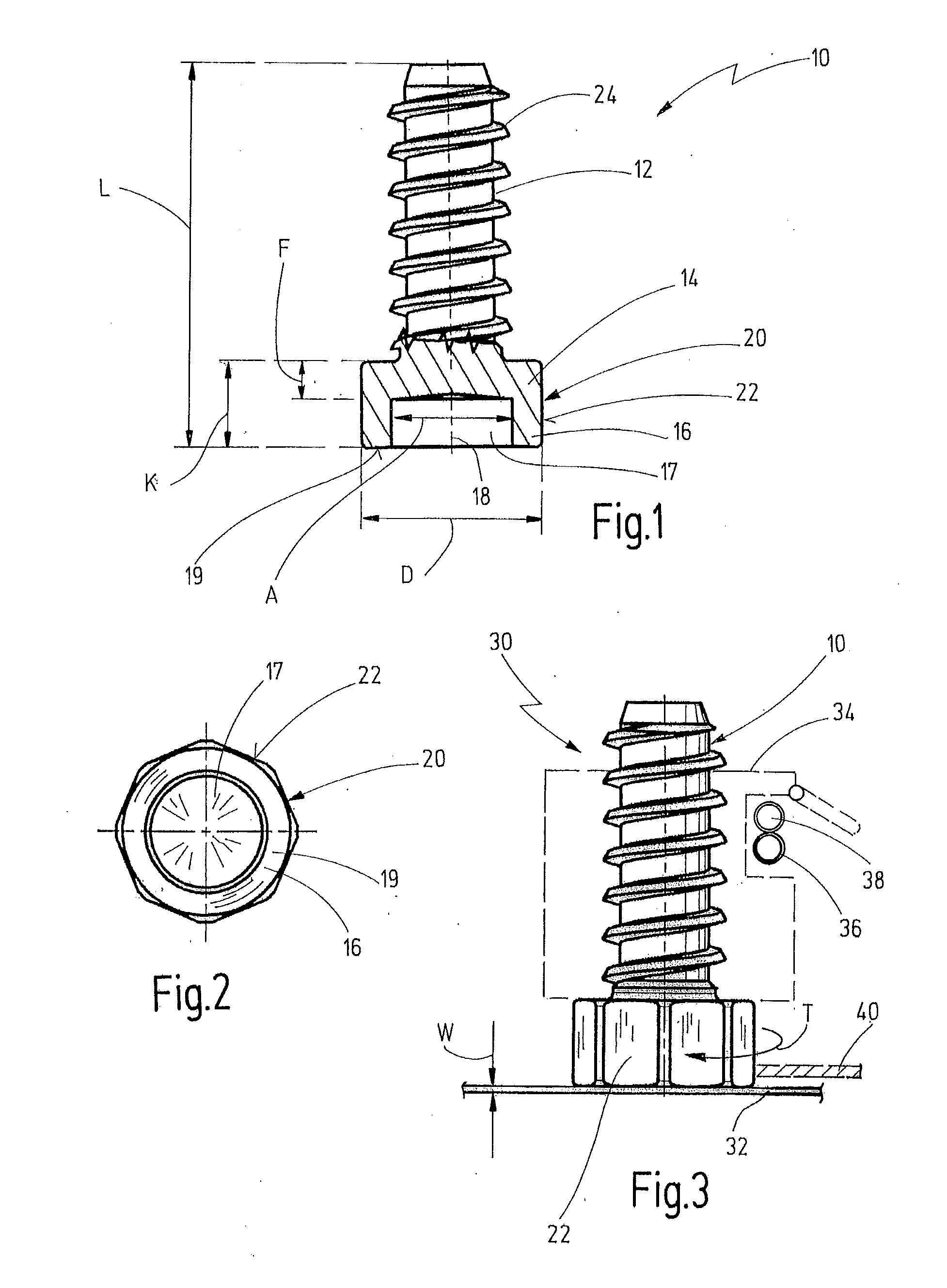
[0040]An embodiment of a stud according to the invention is designated generally by 10 in FIGS. 1 and 2.

[0041]The stud 10 has a shank 12, adjoining which in the axial direction is a flange 14. Adjoining the flange 14 in the axial direction is an annular section 16, within which a recess 17 of circular cross section is located.

[0042]A longitudinal axis of the stud 10 is shown at 18.

[0043]A front annular surface 19 is formed on the front end of the annular section 16. The recess 17 extends from the front annular surface 19 up to the flange 14.

[0044]On the whole, the flange 14 and the annular section 16 form a head section 20, the outer circumference of which has a polygonal shape 22, in the present case an octagonal shape.

[0045]A coarse thread 24 is formed on the shank 12. The stud 10 has an overall length L. The axial length of the head section 20 is designated by K in FIG. 1. The axial length of the flange section is designated by F in FIG. 1. An outside diameter of the head section...


PUM

PropertyMeasurementUnit
thicknessaaaaaaaaaa
thicknessaaaaaaaaaa
thicknessaaaaaaaaaa

Abstract

A welding stud includes a shank and a head flange, which projects radially relative to the shank and whose outer circumference is of polygonal design in order to be able to apply a test torque (T) to the stud by means of a tool. The flange includes an annular section (16) whose front facing and radially extending annular surface is designed as a welding surface. The annular section directly adjoins the flange, and the annular section and the flange form a head section which has a uniform outside diameter (D) throughout, and wherein the polygonal shape of the flange extends over the annular section up to its front annular surface.

Description

CROSS REFERENCE TO RELATED APPLICATIONS[0001]This application is a continuation of PCT Application No. PCT / US2009 / 050047, filed Jul. 9, 2009 which claims the benefit of German Application No. 10 2008 033 373.5, filed on Jul. 9, 2008, the disclosure of which is incorporated herein by reference.BACKGROUND OF THE INVENTION[0002]The present invention relates to a stud for stud welding, having a shank, having an axially adjoining flange which projects radially relative to the shank, and having an annular section which axially adjoins the flange and whose front, radially extending annular surface is designed as a welding surface which is to be welded to a workpiece.[0003]The invention also relates to a fastening arrangement having a workpiece and a stud welded to the workpiece and also relates to a method of welding a stud to a workpiece and to the use of such a stud for welding onto a workpiece.[0004]The invention generally concerns the field of stud welding. This welding process is used...

Claims


Application Information

Patent Timeline
Patent Type & Authority Applications(United States)
IPC IPC(8): F16B39/02F16B35/00B23K9/20
CPCB21K1/44B23K9/201B23K9/207B23K35/0288B23K31/125F16B31/02F16B37/061F16B37/06F16B23/0038
Inventor DREXLER, FRANKSCHNEIDER, JOACHIMKORTMANN, HANS-GERHARD
Owner NEWFREY
Why Eureka
Try Eureka