Modular turbine airfoil and platform assembly with independent root teeth

a technology of turbine engine and airfoil, which is applied in the direction of liquid fuel engines, vessel construction, marine propulsion, etc., can solve the problems of angle grain boundaries, casting defects, and disadvantages of one piece casting of blade and platform

Inactive Publication Date: 2011-06-16
SIEMENS ENERGY INC
View PDF20 Cites 47 Cited by
  • Summary
  • Abstract
  • Description
  • Claims
  • Application Information

AI Technical Summary

Problems solved by technology

However, casting the blade and platform in one piece has disadvantages.
The thermal gradient is not optimized when the baffle does not closely fit around the casting and can lead to the formation of casting defects such as low and high angle grain boundaries.
It is also difficult to maintain the single crystal structure in regions where there are large geometric changes in the casting, for example in the fillet region where the airfoil transitions to the platform.
Casting defects such as ‘freckle chains’ are often observed.
Forming the blade and platform as a single piece does not allow material optimization.
However, forming them of separate pieces involves fastening, close tolerances, stress concentrations, and vibration issues.

Method used


Image

  • Modular turbine airfoil and platform assembly with independent root teeth
  • Modular turbine airfoil and platform assembly with independent root teeth
  • Modular turbine airfoil and platform assembly with independent root teeth

Examples


Embodiment Construction

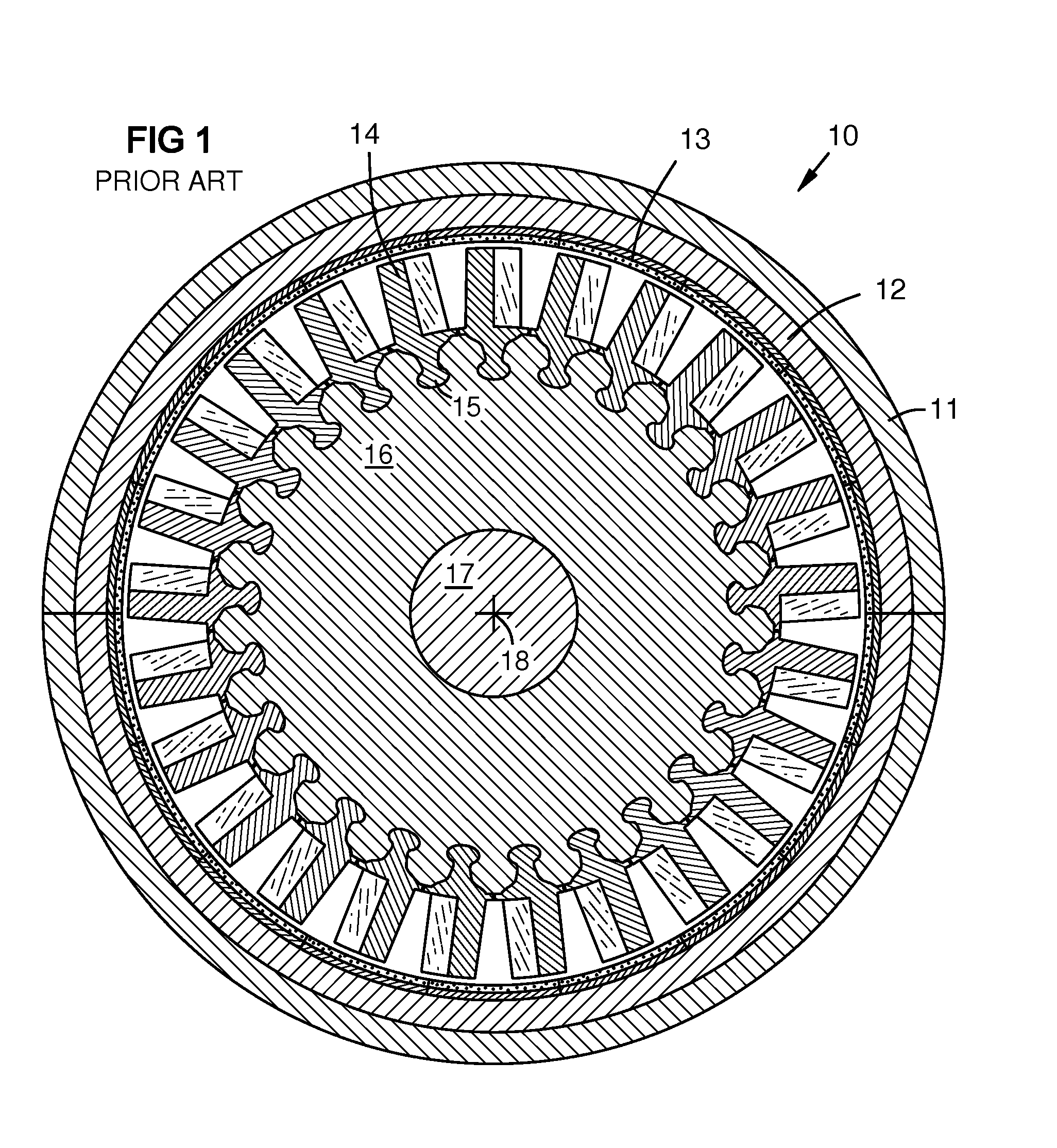
[0015]FIG. 1 shows conceptual sectional view of a known gas turbine engine 10 with a casing 11, a retaining ring 12, and a shroud 13, taken on a section plane through a turbine rotor disk 16. Blades 14 with integral platforms 15 are mounted around the disk using a dovetail joint geometry. The disk is mounted on an axle 17 having a rotation axis 18.

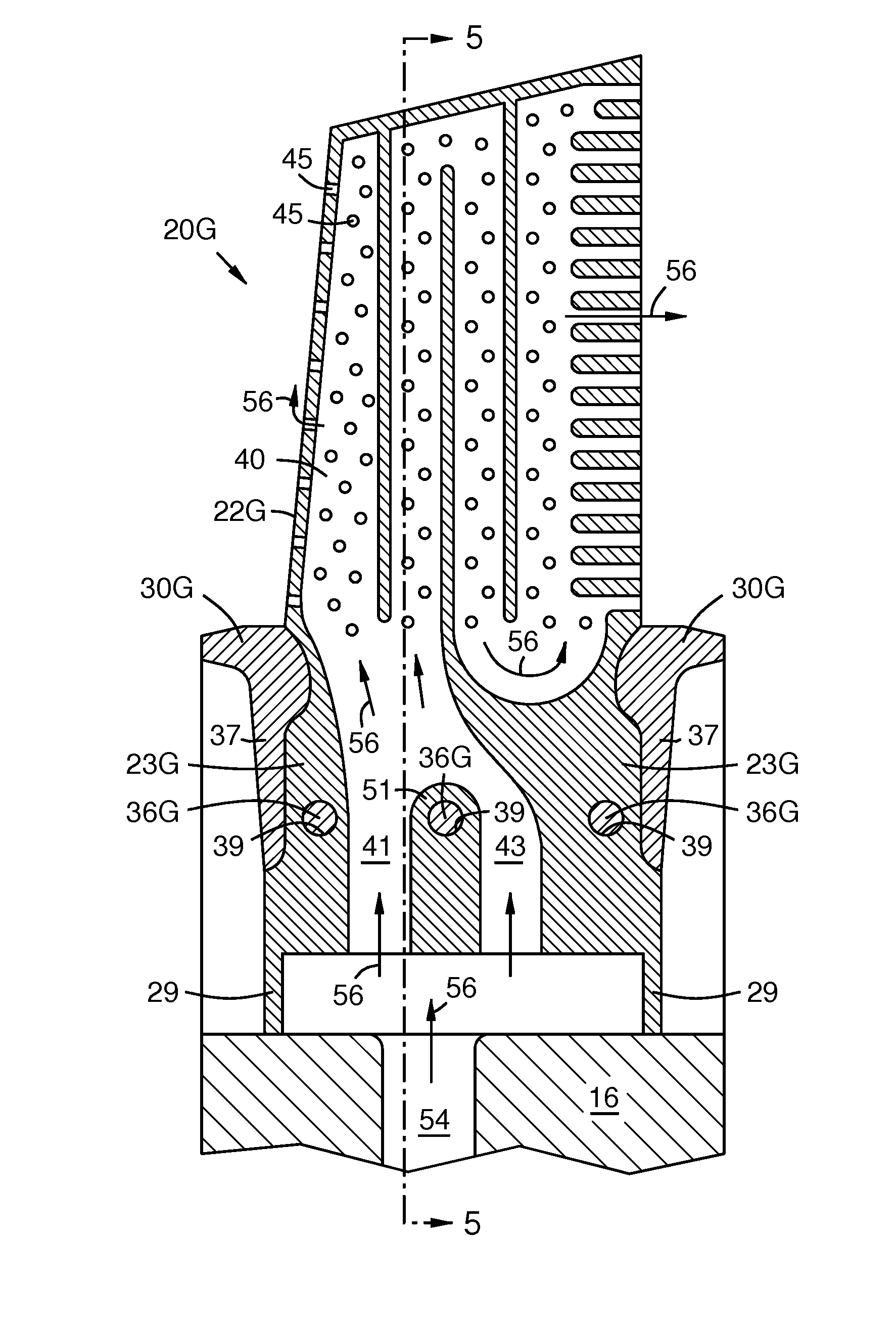
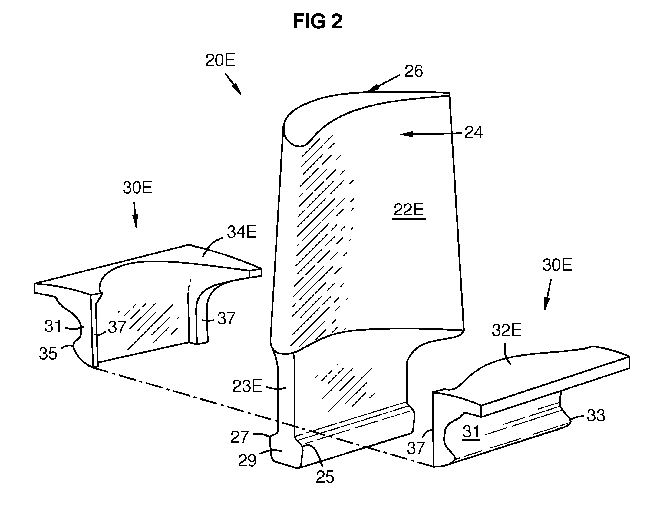
[0016]FIG. 2 shows a turbine blade assembly 20E, including a blade or airfoil 22E having a pressure side 24, a suction side 26, and a shank 23E. A platform 30E has pressure and suction side portions 32E, 34E, and each platform portion has a root portion 31 with at least one laterally extending tooth 33, 35 that engages the rotor disk 16 as later shown. After assembly, the platform 30E brackets (at least partially or completely surrounding) a first portion of the shank 23E. The shank 23E extends below the platform 30E, or radially inward of the platform 30E when mounted in a turbine disk. Herein, “axially” and “radially” are meant in relati...


PUM


Abstract

A turbine airfoil (22E-H) extends from a shank (23E-H). A platform (30E-H) brackets or surrounds a first portion of the shank (23E-H). Opposed teeth (33, 35) extend laterally from the platform (30E-H) to engage respective slots (50) in a disk. Opposed teeth (25, 27) extend laterally from a second portion of the shank (29) that extends below the platform (30E-H) to engage other slots (52) in the disk. Thus the platform (30E-H) and the shank (23E-H) independently support their own centrifugal loads via their respective teeth. The platform may be formed in two portions (32E-H, 34E-H), that are bonded to each other at matching end-walls (37) and / or via pins (36G) passing through the shank (23E-H). Coolant channels (41, 43) may pass through the shank beside the pins (36G).

Description

CROSS-REFERENCE TO RELATED APPLICATIONS[0001]This application is a continuation-in-part of U.S. patent application Ser. No. 12 / 638,034 filed on 15 Dec. 2009 (attorney docket 2009P16191 US) incorporated by reference herein.STATEMENT REGARDING FEDERALLY SPONSORED DEVELOPMENT[0002]Development for this invention was supported in part by Contract No. DE-FC26-05NT42644, awarded by the United States Department of Energy. Accordingly, the United States Government may have certain rights in this invention.FIELD OF THE INVENTION[0003]This invention relates to fabrication and assembly of turbine engine airfoils and platforms, and mounting of such assemblies on a turbine disk.BACKGROUND OF THE INVENTION[0004]Turbine engines have at least one circular array of blades mounted around the circumference of a rotor disk. Each blade can be mounted by forming a mounting platform on the shank of the blade, in which the platform has a dovetail geometry that slides axially into a matching slot in the disk...

Claims


Application Information

Patent Timeline
Patent Type & Authority Applications(United States)
IPC IPC(8): F01D5/18F01D5/00
CPCF01D5/081F01D5/3007F01D5/147F01D11/008
Inventor CAMPBELL, CHRISTIAN X.DAVIES, DANIEL O.ENG, DARRYL
Owner SIEMENS ENERGY INC
Why Eureka
Try Eureka