Fiber optic device with controlled reuse

a fiber optic device and fiber optic technology, applied in the field of fiber optic devices, can solve the problems of optical fiber subject to fracture, laser energy emitted in an undesired direction, unintended tissue, nerve or blood vessel, etc., and achieve the effect of controlling limiting the length of optical fiber

Inactive Publication Date: 2011-06-16
TRIMEDYNE
View PDF3 Cites 97 Cited by
  • Summary
  • Abstract
  • Description
  • Claims
  • Application Information

AI Technical Summary

Benefits of technology

[0011]The present invention provides a novel and improved fiber optic device in which an elongated handpiece for an optical fiber defines an internal, elongated, confined flow passageway with an apertured endwall at a distal end portion of the passageway, and controls the length of optical fiber that can pass through the handpiece. An optical fiber having a distal working end is dispensed through the handpiece and is disposed within the passageway. A stop member, such as a rigid sheath and the like, within the passageway surrounds and is attached to the optical fiber. The stop member limits the length of optical fiber that can pass through the handpiece. The stop member preferably contains a series of index positions for incrementally adjusting the position of the stop member within the passageway and thus the position of the optical fiber working end. The stop member is configured to abut the endwall when the stop member is moved within the internal passageway to a final position.

Problems solved by technology

Laser energy reflected from the tissue can vaporize the protective buffer coating of the optical fiber, however, leaving the optical fiber subject to fracture.
Also, the distal end portion of the optical fiber can be deformed or melted by laser energy reflected from the target tissue, causing laser energy to be emitted in an undesired direction, perhaps affecting an unintended tissue, nerve or blood vessel.
Excessive reuse of fiber-optic devices is not always desirable.
If the card or connector has been recognized before, the microprocessor will not allow the laser to be turned-on.
Since thousands of lasers without such microprocessors have been sold to hospitals, surgery centers and physicians, there is no way to limit the number of reuses of conventional optical fibers with these lasers.
However, if left on standby all day or through one or more nights, the laser's lifetime may be shortened.

Method used


Image

  • Fiber optic device with controlled reuse
  • Fiber optic device with controlled reuse
  • Fiber optic device with controlled reuse

Examples


first embodiment

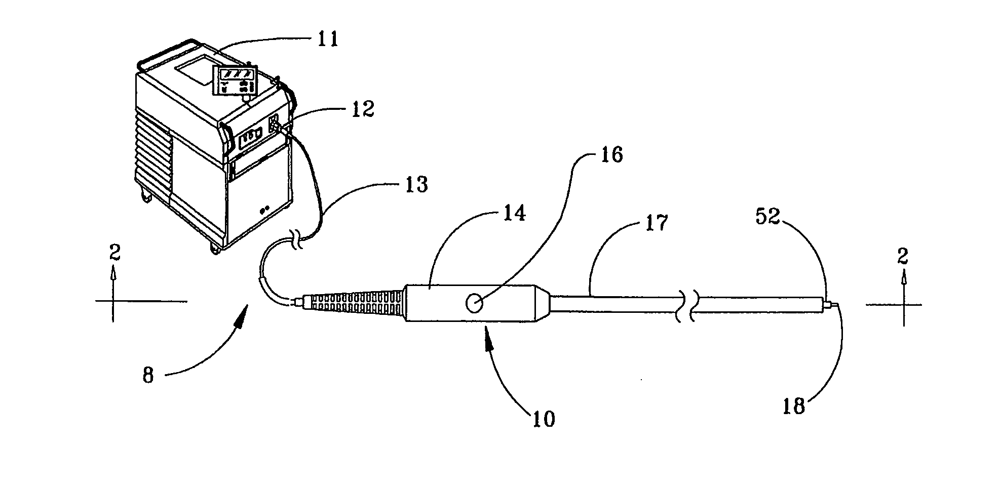
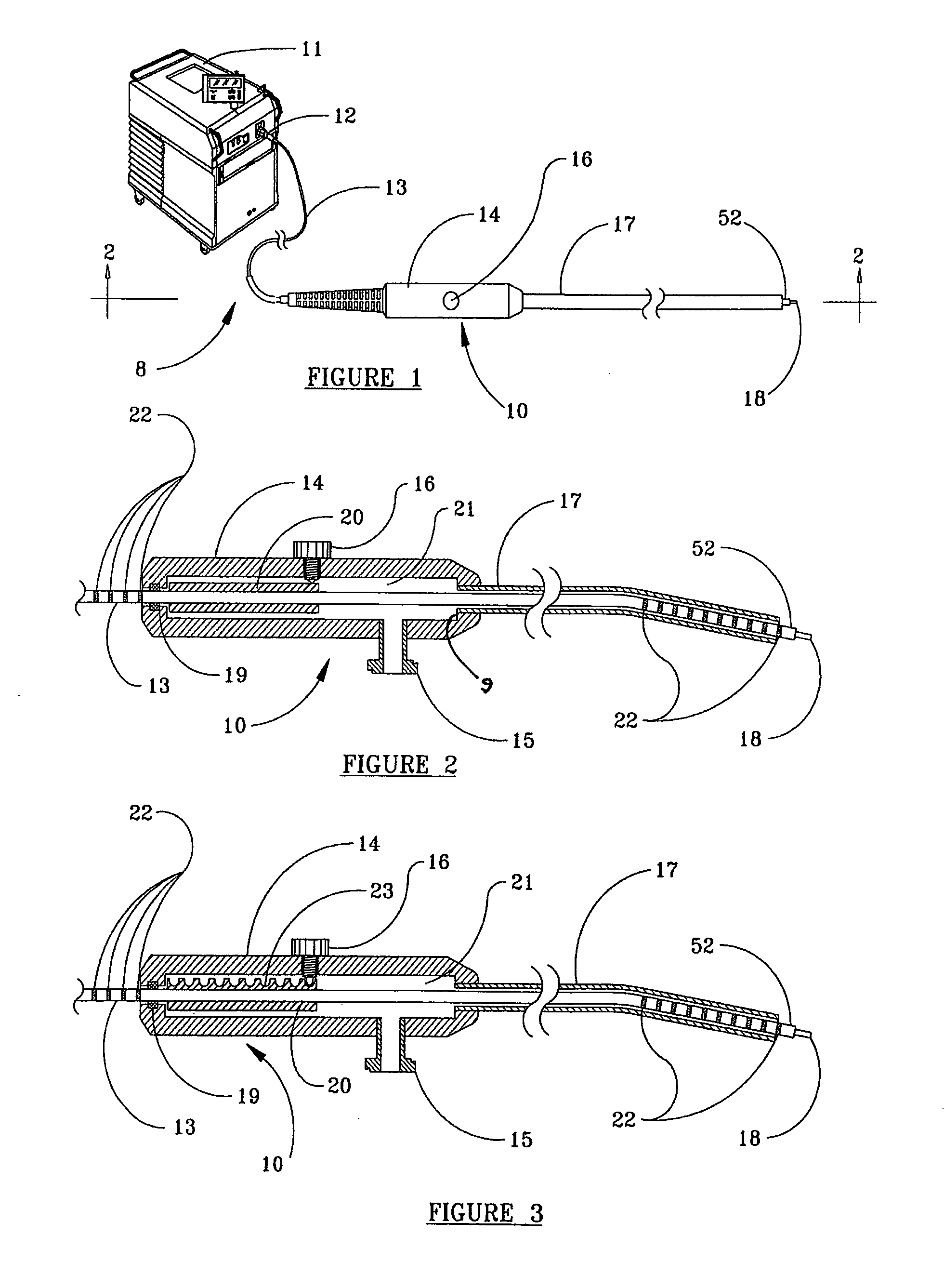
[0028]Referring now to the drawings and initially to FIGS. 1 and 2, a first embodiment is shown in relation to system 8 for delivering laser energy. As seen in FIG. 1, system 8 is comprised of a fiber optic device 10 and a source of laser energy 11. Fiber optic device 10 comprises optical fiber 13, handpiece 14, and a connector 12 that optically couples optical fiber 13 to the source of laser energy 11. Optical fiber 13 has core 18 surrounded by a buffer coating 52, and extends through an optional rubber or plastic strain relief, as known in the art, and through an enclosing body or handpiece 14. A fiber advancement mechanism is associated therewith. Handpiece 14 is preferably made of a sturdy metal, such as medical grade stainless steel, or a rigid, durable plastic, such as acetal homopolymer resin, available from Interstate Plastics, Sacramento, Calif. Handpiece 14 is comprised of two halves, which can be joined together with a locking mechanism, screws and / or an adhesive.

[0029]Op...

second embodiment

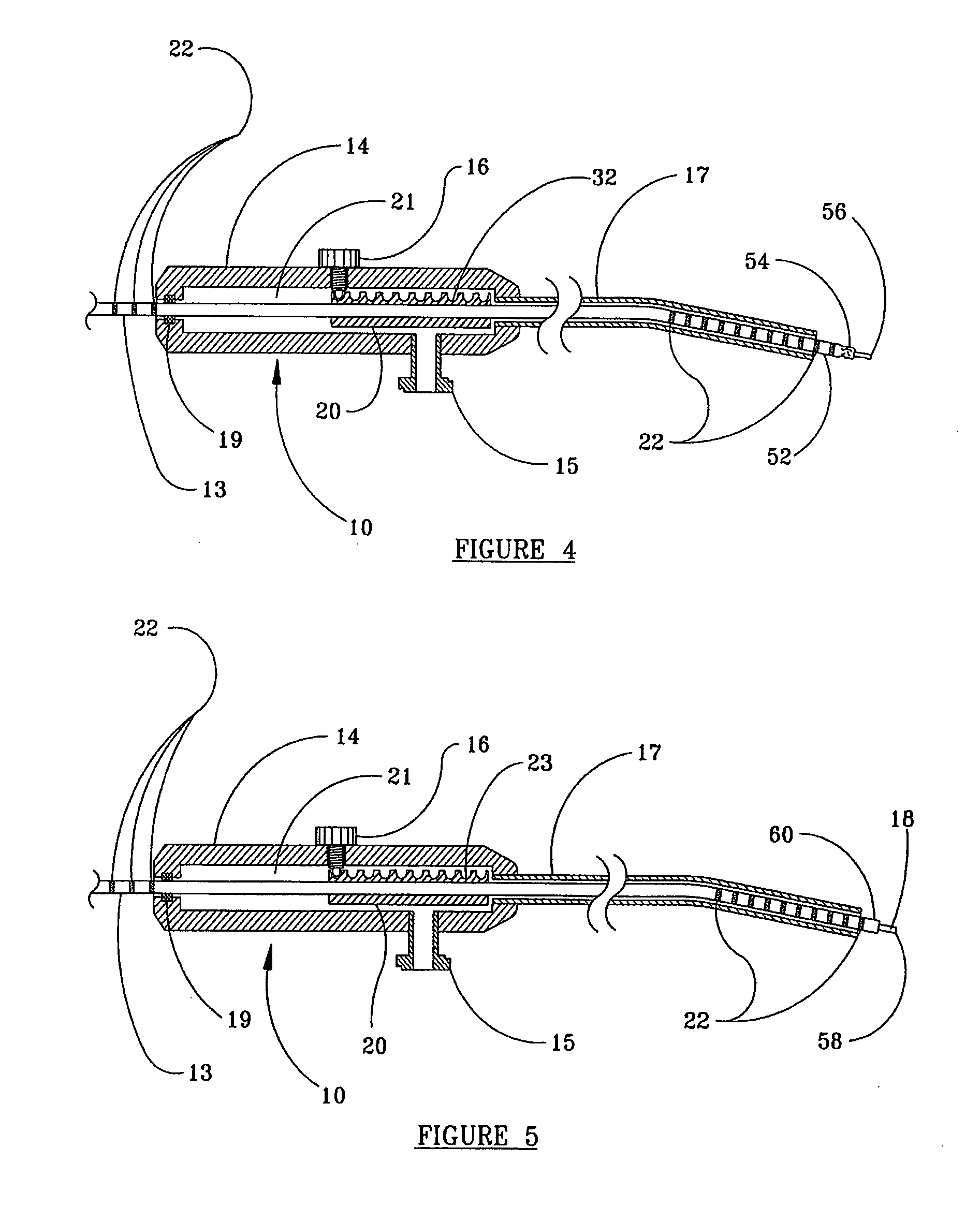
[0038]As illustrated in FIGS. 3-5, in the present invention, sheath 20 has indexing capability in the form of an array of adjacent indentations 23 on its upper surface, opposite set screw 16. Set screw 16 may be provided with a rounded tip that enters one of indentations 23 to removably fix the optic fiber 13 in place within handpiece 14. Preferably the tip of set screw 16 and the indentations 23 are complementary. The number of indentations 23 in the array preferably corresponds to the number of intended uses of device 10, as described heretofore. The spaces between the centers of indentations 23 are preferably equal to the amount of intended protrusion of optical fiber 13 from the free end of cannula 17, i.e., length of advance of buffer coating 52 and core 18 of optical fiber 13 after each use. The spacing of indentations provides a convenient indexing of the optical fiber as it is readied for shortening of its free end, prior to a subsequent use. As shown in FIG. 3, the distal e...

third embodiment

[0042]FIG. 6 illustrates the present invention. In this embodiment, handpiece 14 has two viewing slots for the stop member on its top surface, one distal to expose sheath 20 that receives set screw 16, and a second, proximal slot 24. In the preferred embodiment, these slots are covered by a transparent glass or clear plastic insert and sealed with a gasket material, as known in the art, to provide a window so that sheath 20 and indentations 23 can be viewed by a user, while preventing leakage of fluid.

[0043]Optionally, slot 24 may be provided in one or both sides of handpiece 14, extending throughout most of the length of handpiece 14, to provide the functionality of the two slots shown in FIG. 6. When thus constructed, the single slot formed in handpiece 14 is filled by a glass or clear plastic insert and sealed with a gasket material as described above, to enable the operator to fully view sheath 20 and indentations 23.

[0044]In the embodiment shown in FIG. 6, sheath 20 with indent...


PUM


Abstract

A fiber optic device includes an optical fiber passing through a handpiece that defines an internal passageway with an apertured endwall at a distal end of the passageway. A portion of the optical fiber is disposed within the passageway, and a stop member, such as a rigid sheath, within the passageway is attached to the optical fiber. An indexing member releasably engages the rigid sheath to maintain the rigid sheath at a predetermined position within the passageway. The rigid sheath preferably contains a series of index positions for incrementally adjusting the position of the sheath within the passageway. The rigid sheath is slidably mounted in the passageway and is configured to interfere with the endwall when the rigid sheath is released for movement within the internal cavity to its final position within the passageway.

Description

FIELD OF THE INVENTION[0001]The present invention relates to fiber optic devices, whose frequency of use can be controlled, and especially to such devices suitable for use in a medical procedure.BACKGROUND OF THE INVENTION[0002]Optical fibers, sometimes called fiber-optics, are used to transmit laser energy in a wide variety of medical and surgical procedures to vaporize, cut, coagulate, shrink and denature tissue. The ability to create a variety of tissue effects by varying the amount or wavelength of the laser energy being delivered makes optical fibers a desirable means for delivering laser energy through body orifices or tiny punctures, instead of larger incisions, which are necessary for the use of laser energy not transmittable through optical fibers or other surgical tools.[0003]Optical fibers typically consist of a fused silica or quartz core, which is covered by a thin glass cladding, which is further encased by a relatively thicker buffer coating of a fluorocarbon or a sim...

Claims


Application Information

Patent Timeline
Patent Type & Authority Applications(United States)
IPC IPC(8): A61B18/22
CPCA61B18/22A61B2018/00196A61B2019/4873A61B2019/304A61B2018/2288A61B2018/2244A61B2090/034A61B2090/0814
Inventor LOEB, MARVIN P.
Owner TRIMEDYNE
Why Eureka
Try Eureka