Total artificial heart

a total artificial heart and heart technology, applied in the field can solve the problems of large unmet need, unsustainable development of total artificial heart, and hundreds of thousands of deaths annually, and achieve the effect of preventing stagnation and thrombosis

Active Publication Date: 2011-06-16
OREGONHEART
View PDF4 Cites 26 Cited by
  • Summary
  • Abstract
  • Description
  • Claims
  • Application Information

AI Technical Summary

Benefits of technology

[0020]Radial support of the rotor will be provided by the action of a hydrodynamic bearing between the surface of the housing bore and the outer surface of the rotor wherein blood will be the hydrodynamic fluid. Internal pressure gradients will provide leakage flow within the journal bearing clearances to prevent stagnation and thrombus formation. Axial constraint of the rotor will be a combination of a passive axial magnetic bearing and hydrodynamic thrust bearings.

Problems solved by technology

Congestive heart failure is a major, rapidly growing public health problem that results in hundreds of thousands of deaths annually.
However, donor hearts are limited to about 2,000 per year in the United States and, consequently, there is a large unmet need for approximately 75,000 patients who would benefit from cardiac transplantation, but for whom no donor heart is available.
LVAD's such as these are gaining clinical acceptance, but development of total artificial hearts (TAH) has not kept pace, particularly for permanent assistance without intention to bridge to cardiac transplantation.
Two total artificial hearts are clinically available on a very limited basis in the United States.
The anatomical compatibility of these devices has limited their use to larger patients, since positive displacement pumps are inherently large.

Method used


Image

  • Total artificial heart
  • Total artificial heart
  • Total artificial heart

Examples


embodiment 1

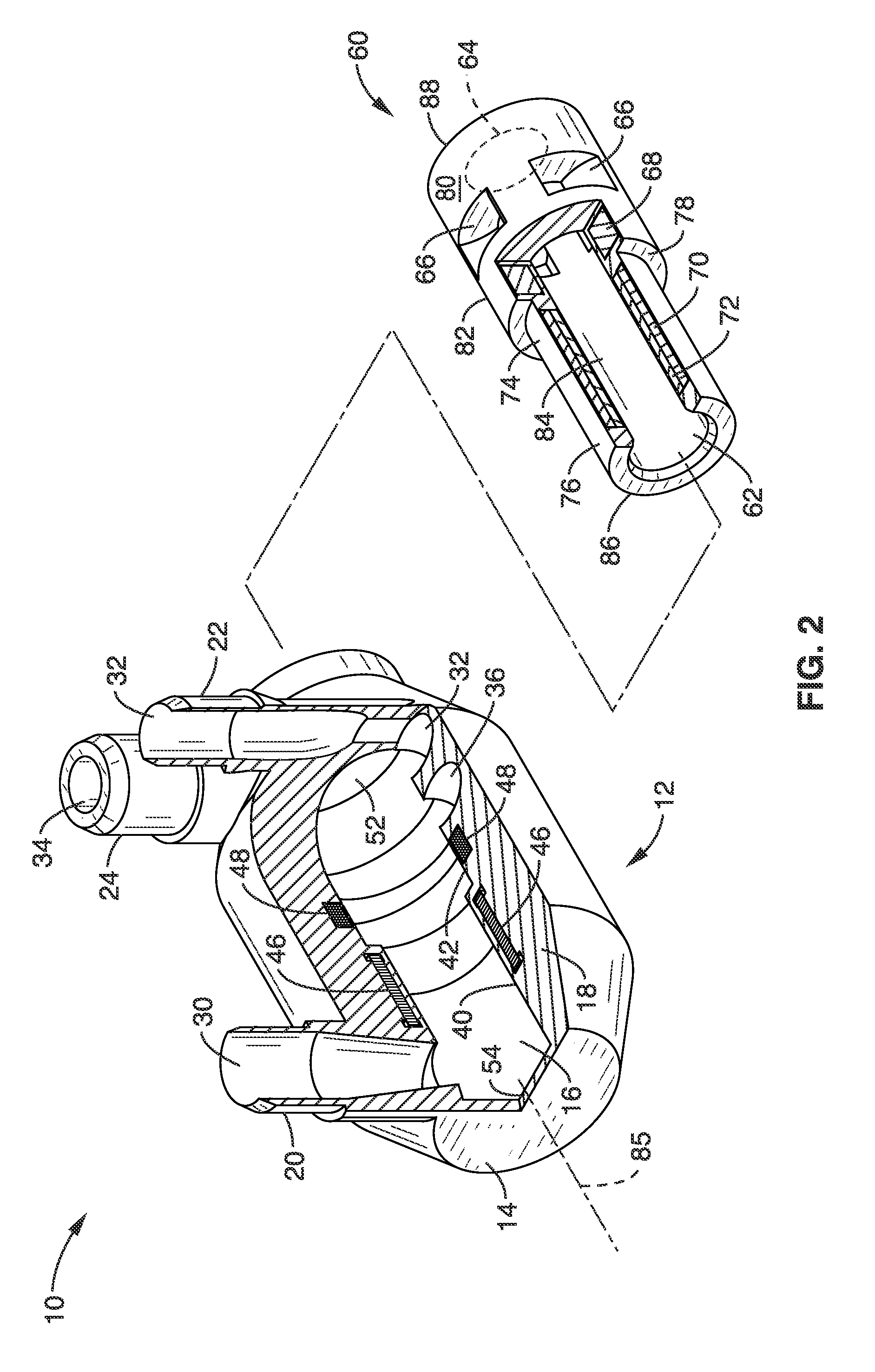
[0061]2. A total artificial heart as recited in wherein in the first position, the rotor is configured to block flow to and from the third and fourth vascular connectors; and wherein in the second position, the rotor is configured to block flow to and from the first and second vascular connectors.

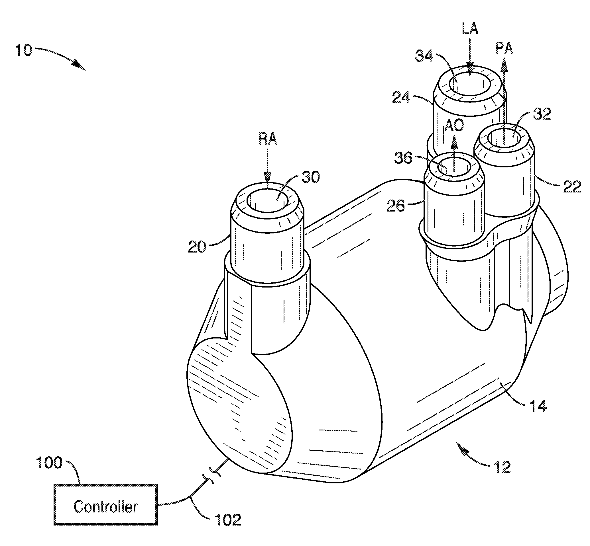
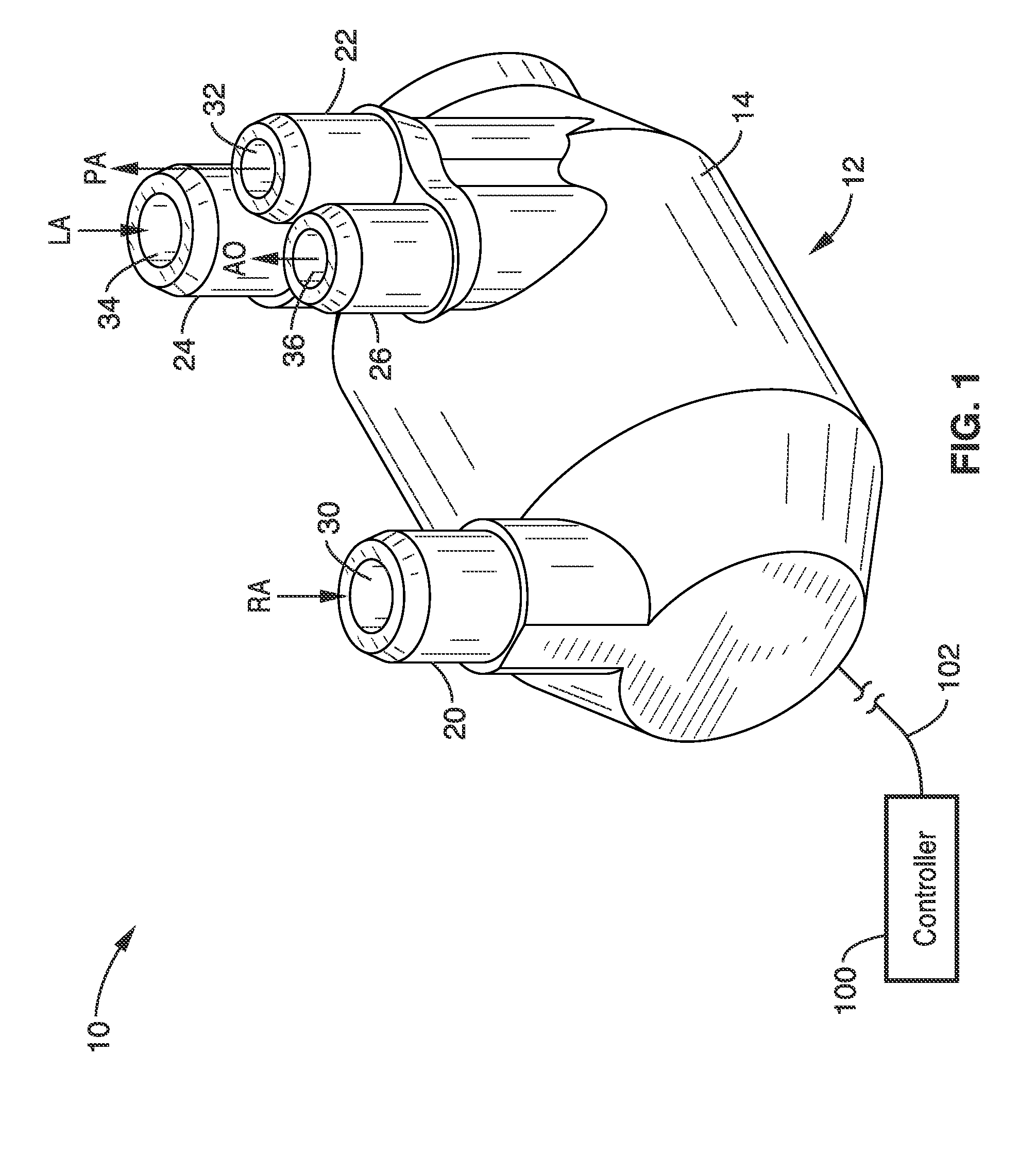
[0062]3. A total artificial heart as recited in embodiment 1: wherein the first vascular connector comprises a left atrium (LA) connector, the second vascular connector comprises an aorta (AO) connector, the third vascular connector comprises a right atrium (RA) connector, the fourth vascular connector comprises a pulmonary artery (PA) connector; and wherein the rotor shuttles between the first position and the second position to alternate the output flow between systemic and pulmonary circulation.

embodiment 3

[0063]4. A total artificial heart as recited in embodiment 3, wherein the first volume of blood is output into arterial circulation, and the second volume of blood is input from venous circulation.

[0064]5. A total artificial heart as recited in embodiment 1, further comprising: a motor stator disposed within the pump housing; and a first magnet disposed within the rotor; wherein the first magnet is responsive to a magnetic field generated by said motor stator to drive rotation of said rotor about said central axis.

embodiment 5

[0065]6. A total artificial heart as recited in embodiment 5, further comprising: a solenoid disposed within the pump housing; and a second magnet disposed within the rotor; wherein the second magnet is responsive to a magnetic field generated by said solenoid to drive axial translation of said rotor from the first position to the second position.


PUM


Abstract

A total artificial heart having a rotor with an impeller, wherein the rotor is mounted within a pump housing on a hollow shaft. The rotor is magnetically driven to produce rotary motion of the impeller for pumping blood. The motor is disposed within the pump housing such that axial translation within the housing acts as a shuttle valve to alternate flow between pulmonary and systemic circulation.

Description

CROSS-REFERENCE TO RELATED APPLICATIONS[0001]This application claims priority from U.S. provisional application Ser. No. 61 / 266,405 filed on Dec. 3, 2009, incorporated herein by reference in its entirety.STATEMENT REGARDING FEDERALLY SPONSORED RESEARCH OR DEVELOPMENT[0002]Not ApplicableINCORPORATION-BY-REFERENCE OF MATERIAL SUBMITTED ON A COMPACT DISC[0003]Not ApplicableNOTICE OF MATERIAL SUBJECT TO COPYRIGHT PROTECTION[0004]A portion of the material in this patent document is subject to copyright protection under the copyright laws of the United States and of other countries. The owner of the copyright rights has no objection to the facsimile reproduction by anyone of the patent document or the patent disclosure, as it appears in the United States Patent and Trademark Office publicly available file or records, but otherwise reserves all copyright rights whatsoever. The copyright owner does not hereby waive any of its rights to have this patent document maintained in secrecy, includ...

Claims


Application Information

Patent Timeline
Patent Type & Authority Applications(United States)
IPC IPC(8): A61M1/12A61M60/196A61M60/242A61M60/422A61M60/515A61M60/82A61M60/824A61M60/825
CPCA61M1/122A61M1/101A61M2205/3334A61M60/824A61M60/422A61M60/148A61M60/196A61M60/515A61M60/242A61M60/825A61M60/419
Inventor WAMPLER, RICHARD
Owner OREGONHEART
Why Eureka
Try Eureka