
Engine Control with Valve Operation Monitoring Using Camshaft Position Sensing

Active Publication Date: 2011-06-16
FORD GLOBAL TECH LLC
View PDF11 Cites 41 Cited by
  • Summary
  • Abstract
  • Description
  • Claims
  • Application Information

AI Technical Summary

Benefits of technology

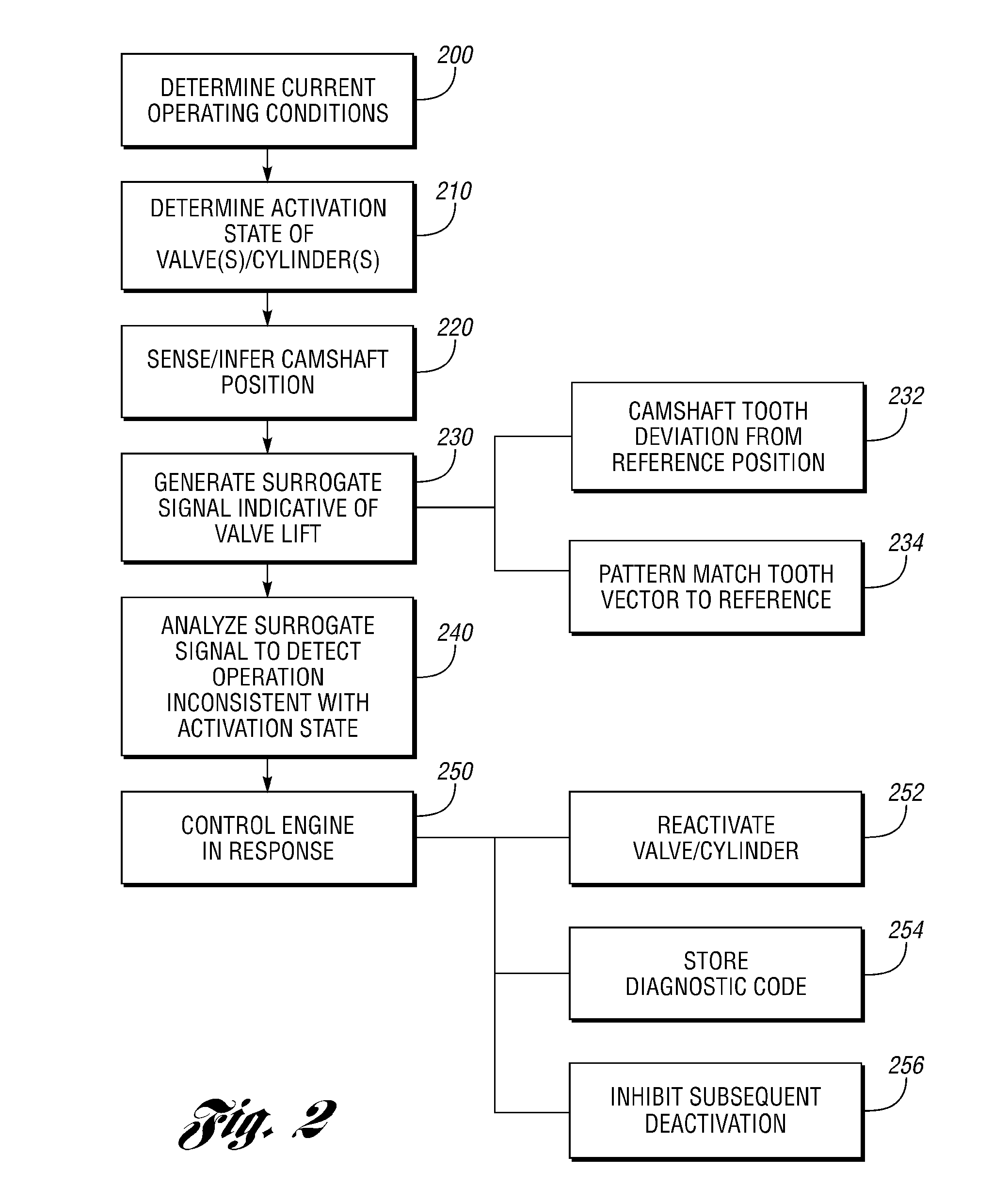
[0007]Those of ordinary skill in the art will recognize a number of advantages associated with various embodiments according to the present disclosure. For example, monitoring operation of valve deactivation using an existing camshaft sensor provides diagnostics and control without the necessity of an additional dedicated sensor. Systems and methods according to the present disclosure may be used for detecting various types of anomalous operation including valve operation (lifting) while deactivated as well as valves remaining closed after activation. Camshaft signal processing according to the present disclosure may be continuously performed rather than being triggered in response to a state or mode change. Monitoring of valve deactivation according to embodiments of the present disclosure may reduce or eliminate degradation in drivability, NVH (noise, vibration, harshness), fuel economy or component durability otherwise associated with valves or cylinders that do not respond as desired.

Problems solved by technology

Such conditions may result in degraded drivability, increased NVH (noise, vibration, harshness), reduced fuel economy, or component degradation, for example.

Method used


Image

  • Engine Control with Valve Operation Monitoring Using Camshaft Position Sensing
  • Engine Control with Valve Operation Monitoring Using Camshaft Position Sensing
  • Engine Control with Valve Operation Monitoring Using Camshaft Position Sensing

Examples


Embodiment Construction

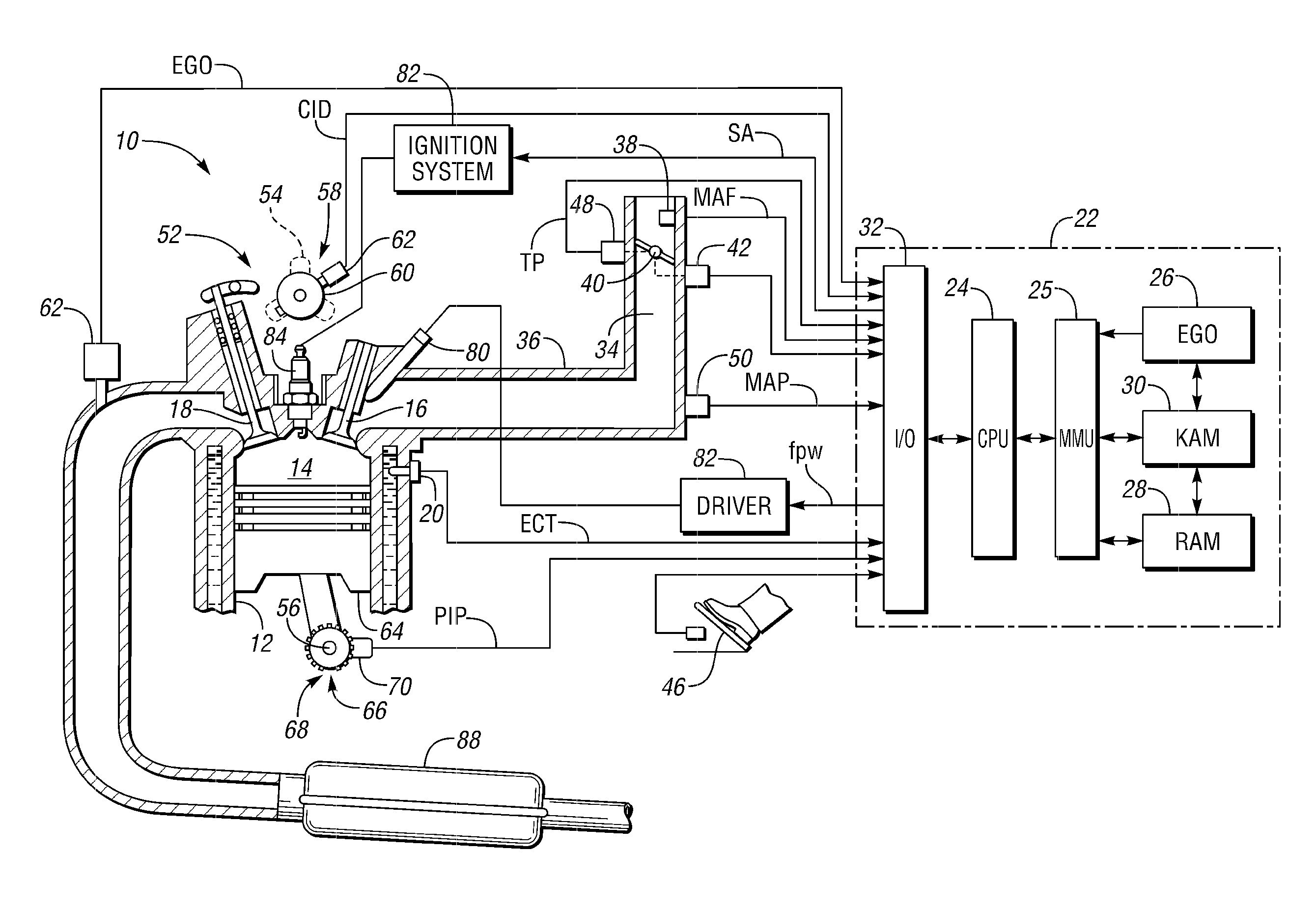
[0018]As those of ordinary skill in the art will understand, various features of the embodiments illustrated and described with reference to any one of the Figures may be combined with features illustrated in one or more other Figures to produce alternative embodiments that are not explicitly illustrated or described. The combinations of features illustrated provide representative embodiments for typical applications. However, various combinations and modifications of the features consistent with the teachings of the present disclosure may be desired for particular applications or implementations. The representative embodiments used in the illustrations relate generally to a four-stroke, multi-cylinder, port injected internal combustion engine operable in a variable displacement mode with mechanically actuated intake and / or exhaust valves and an electronically controlled throttle valve. Those of ordinary skill in the art may recognize similar applications or implementations with oth...


PUM


Abstract

A system or method for controlling a multiple cylinder internal combustion engine operable in a reduced displacement mode with at least one valve or cylinder selectively deactivated include monitoring valve operation by analyzing camshaft position to detect valve operation inconsistent with a current cylinder state (activated or deactivated) and controlling the engine in response to detecting the inconsistent operation. The camshaft position may be used to produce a surrogate signal indicative of intake / exhaust valve lift generated using camshaft sensor tooth deviation relative to an expected or reference tooth position for a corresponding crankshaft position and compared to a corresponding threshold. The surrogate signal indicative of valve lift may also be generated by pattern matching or correlation of one or more reference tooth position patterns to a measured or inferred tooth position pattern.

Description

BACKGROUND[0001]1. Technical Field[0002]Systems and methods for monitoring valve operation in an internal combustion engine using camshaft position sensing.[0003]2. Background Art[0004]Fuel economy for a multi-cylinder internal combustion engine can be improved by deactivating some of the engine cylinders under certain operating conditions. Reducing the number of operating cylinders reduces the effective displacement of the engine when operating in a reduced displacement mode such that it is sometimes referred to as a variable displacement engine. Depending upon the particular configuration of the variable displacement engine, one or more cylinders may be selectively deactivated to improve fuel economy under light-to-moderate load conditions, for example. In some engine configurations, a group of cylinders, which may be an entire bank of cylinders, is selectively deactivated. Cylinder deactivation may include deactivation of intake valves, exhaust valves, or both depending upon the ...

Claims


Application Information

Patent Timeline
IPC IPC(8): F02D28/00
CPCF02B2275/16F02D13/06Y02T10/18F02D41/009F02D41/0087Y02T10/12
Inventor ROLLINGER, JOHN ERICWADE, ROBERT ANDREWDOERING, JEFFREY ALLENSZWABOWSKI, STEVEN JOSEPH
Owner FORD GLOBAL TECH LLC
Learn More