Method and system for pre-ignition control

a vehicle engine and pre-ignition control technology, applied in the direction of electric control, machines/engines, instruments, etc., can solve the problems of increased exhaust emissions, reduced combustion efficiency, and increased exhaust emissions, so as to reduce the degree of leanness and duration of enleanment, and increase the richness and/or duration of preceding enrichment.

Active Publication Date: 2011-06-16
FORD GLOBAL TECH LLC
View PDF11 Cites 43 Cited by
  • Summary
  • Abstract
  • Description
  • Claims
  • Application Information

AI Technical Summary

Benefits of technology

Following the enrichment, the cylinder may be operated lean, the enleanment based on the preceding enrichment. For example, as a degree of richness and / or duration of the preceding enrichment increases, the degree of leanness and duration of the enleanment may be increased. As such, the preceding pre-ignition mitigating enrichment can lead to a drop in exhaust feedgas oxygen content, which can, in turn, degrade the catalytic efficiency of an emission control device catalytic converter, thereby degrading exhaust emissions. By enleaning the cylinder based on the enrichment, exhaust feed-gas oxygen levels may be returned within catalyst operational ranges, and improving exhaust emissions. Following the enleanment, the cylinder may resume stoichiometric operation.
The pre-ignition count may include, for example, a cylinder lifetime pre-ignition count (that is, a count of a total number of pre-ignition events over the life of each cylinder of the engine), a cylinder trip pre-ignition count (that is, a count of total number of pre-ignition events in each cylinder over the current engine cycle), an engine pre-ignition count (that is, a count of total number of pre-ignition events in the engine), as well as a consecutive pre-ignition count (that is, a count of a total number of consecutive and uninterrupted pre-ignition events over a plurality of consecutive combustion events). The enrichment and load limiting may also be adjusted differently based on the different pre-ignition counts. In one example, a more aggressive approach may be taken in response to the cylinder trip pre-ignition count exceeding a threshold (such as, by enriching more rich and / or for a longer duration, and by limiting more load) as compared to the cylinder lifetime pre-ignition count exceeding a threshold (such as, by enriching less rich and / or for a shorter duration, and by limiting less load). In another example, the load limiting and enrichment may be of a smaller amount when the cylinder pre-ignition count exceeds a threshold and by a larger amount when the engine pre-ignition count exceeds a threshold. In still another example, as the consecutive pre-ignition count exceeds a threshold, load limiting as well as a degree of richness and duration of the enrichment may be increased.

Problems solved by technology

Under certain operating conditions, engines that have high compression ratios, or are boosted to increase specific output, may be prone to low speed pre-ignition combustion events.
The early combustion due to pre-ignition can cause very high in-cylinder pressures, and can result in combustion pressure waves similar to combustion knock, but with larger intensity.
Consequently, pre-ignition mitigating steps that are effective for the cylinder with the fewer number of past pre-ignition events may not be as effective for the cylinder with the larger number of past pre-ignition events.
For example, the engine load may be limited more as a number of previous pre-ignition events increases.
However, even after preemptively limiting the engine load, cylinder pre-ignition may occur.
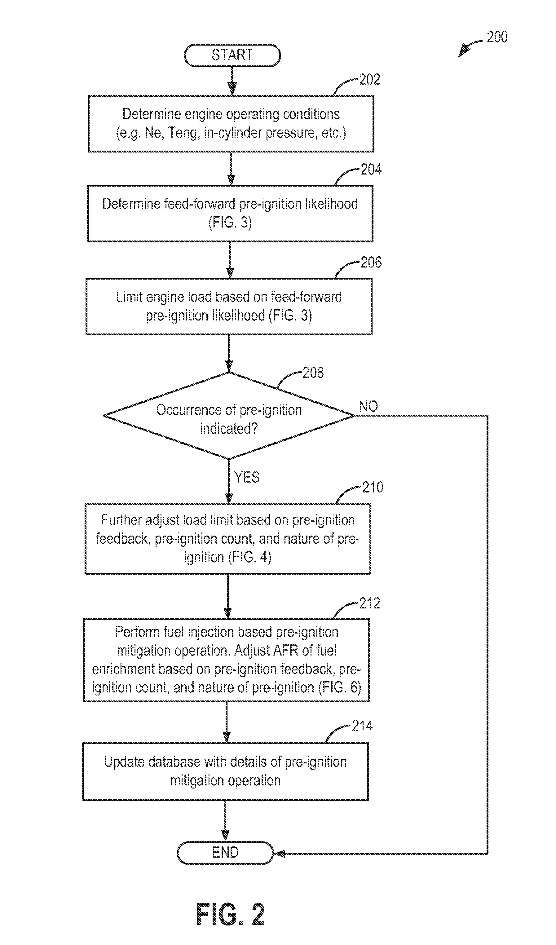
At the same time, the engine load may also be further limited based on the pre-ignition count.
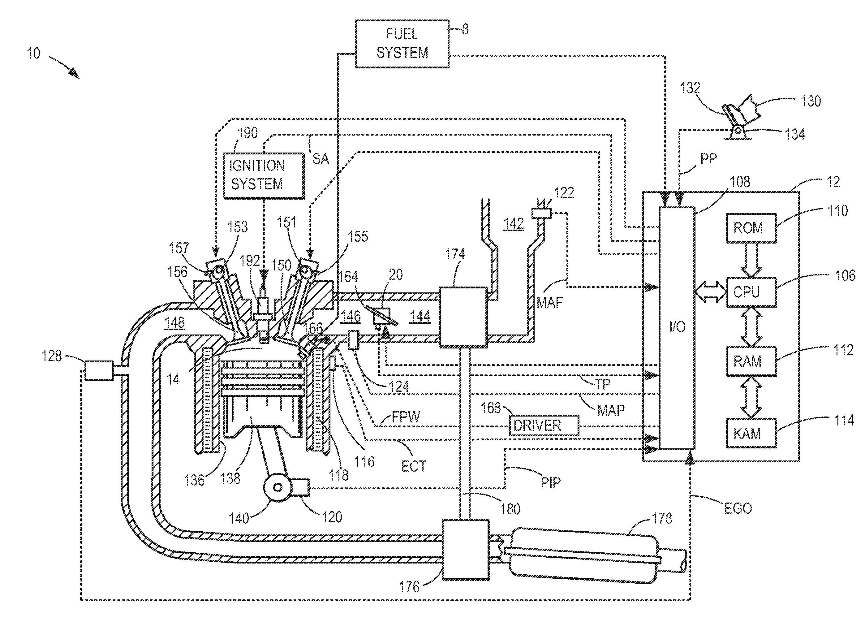
For example, engine load may be limited by reducing air flow to the cylinder, such as by reducing a throttle opening, reducing engine boost, and / or adjusting a cam timing.
However, the effect of load limiting on pre-ignition may be delayed until a stable air flow is reached.
Further still, in addition to the enrichment and load limiting, spark timing may be advanced by an amount.
As such, the preceding pre-ignition mitigating enrichment can lead to a drop in exhaust feedgas oxygen content, which can, in turn, degrade the catalytic efficiency of an emission control device catalytic converter, thereby degrading exhaust emissions.

Method used


Image

  • Method and system for pre-ignition control
  • Method and system for pre-ignition control
  • Method and system for pre-ignition control

Examples


example enrichment

and enleanment profiles, as described previously, are now explained in the example fuel injection operations of FIGS. 8-9.

First turning to FIG. 8, map 800 depicts a first example pre-ignition mitigating operation according to the present disclosure. An air-to-fuel ratio (AFR) of the injected fuel mixture is shown along the y-axis while time is depicted over the x-axis. As shown, before t1, the fuel mixture injected inside a cylinder may be substantially at stoichiometry. At t1, in response to pre-ignition indication 801, the affected cylinder may be operated with a first air-to-fuel ratio AFR1 richer than stoichiometry for a first duration 804. The degree of richness 806 of the injection and the first duration 804 may be adjusted based on engine operating conditions at the time of the pre-ignition indication 801. After the first duration has elapsed, at t2, a controller may be configured to determine an amount of excess fuel injected over the first enrichment operation. As such, the...


PUM


Abstract

Methods and systems are provided for mitigating engine pre-ignition based on a feed-forward likelihood of pre-ignition and feedback from a pre-ignition event. In response to an indication of pre-ignition, a cylinder may be enriched while an engine load is limited. The enrichment may be followed by an enleanment to restore exhaust catalyst feed-gas oxygen levels. The mitigating steps may be adjusted based on engine operating conditions, a pre-ignition count, as well as the nature of the pre-ignition.

Description

FIELDThe present description relates generally to methods and systems for controlling a vehicle engine in response to pre-ignition detection.BACKGROUND / SUMMARYUnder certain operating conditions, engines that have high compression ratios, or are boosted to increase specific output, may be prone to low speed pre-ignition combustion events. The early combustion due to pre-ignition can cause very high in-cylinder pressures, and can result in combustion pressure waves similar to combustion knock, but with larger intensity. Strategies have been developed for prediction and / or early detection of pre-ignition based on engine operating conditions. Additionally, following detection, various pre-ignition mitigating steps may be taken.The inventors herein have recognized that a cylinder's propensity for pre-ignition may not only be affected by engine operating conditions, but also by a cylinder's pre-ignition history. For example, a cylinder that has already had a larger number of previous pre-...

Claims


Application Information

Patent Timeline
Patent Type & Authority Applications(United States)
IPC IPC(8): F02D41/30
CPCF02D35/02F02D35/027Y02T10/42F02D41/008F02D41/40F02D41/0002F02D43/00F02D35/021Y02T10/40
Inventor ROLLINGER, JOHN ERICGLUGLA, CHRIS PAULJENTZ, ROBERT ROYBASKINS, ROBERT SAROWWILLARD, KAREN
Owner FORD GLOBAL TECH LLC
Why Eureka
Try Eureka