[0013]Lasering represents a tried and tested method nowadays. Lasering makes it possible to produce electrodes with an arbitrarily complex structure, which are insulated from one another.
Laser ablation of an arbitrary structure, for example a circle as a circular electrode surface on the one hand, and the screw material as the back electrode on the other hand, makes it possible to obtain the ultrasound sensor. One electrode is constituted by the
laser-ablated surface, for example formed as a
circular surface, while the back electrode is constituted by the material of the connection component. Whereas only simple structures can be produced by the manual masking method outlined above in connection with the prior art, structures having much more complex geometries can be fabricated by
laser ablation, even entire sensor arrays, which cannot be produced by the manual masking method. In particular, by
laser ablation of the at least one electrode in order to produce the ultrasound sensor, the latter can be adapted to the structure of the component, for example to the geometry of a screw or bolt or
rivet head. A very wide variety of connection elements, for example screws, bolts, rivets or tie-rods or the like, can be provided with at least one ultrasound sensor on one of the end sides. Instead of one ultrasound sensor on the end sides, groups of sensors or entire sensor arrays can also be produced by means of the
laser ablation of electrodes. It is thus in particular very readily possible to adapt the sensor structure, i.e. its geometry, optimally to the connection element. By laser
ablation of electrode structures with a complex geometry, ultrasound sensors can be applied onto connection elements having longitudinal or transverse bores, for example screws or hollow bolts. In the case of components having a longitudinal bore, which are primarily stressed by shearing, a ring electrode, which is arranged around the bore, is made from an electrode originally having a circular appearance, which is used for example for connection elements without a through-bore. An adapted sensor structure can furthermore be made, for example for connection elements which have two transverse bores crossing in the direction of the axes. In this case, by the laser ablation of the electrodes as proposed according to the invention, it is possible to ensure that the ultrasound sensors are not arranged above intersecting bores in the material of the connection component, but instead where the propagation of the ultrasound
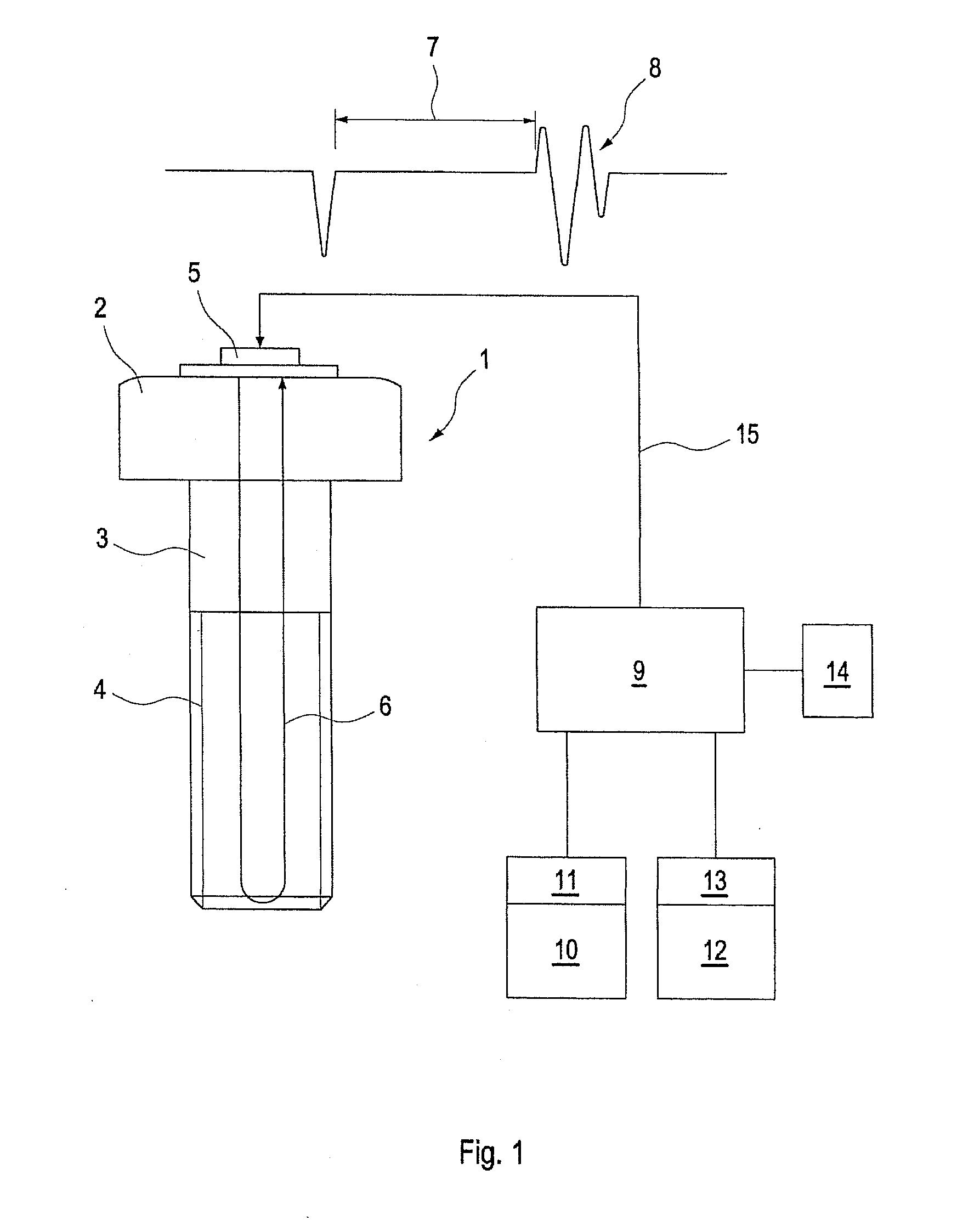
signal is not hindered by the transverse bores so that the applied
ultrasound pulse delivers a meaningful and evaluable
echo signal.
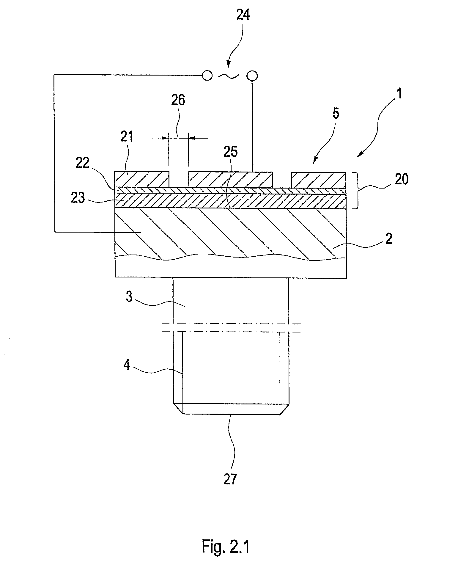
[0019]When laser-ablating the at least one electrode with a complex and arbitrary geometry, after
erosion of the top cover layer it is necessary to ensure that the underlying
layers are not damaged. The
erosion behaviour when lasering depends on the
absorption capacity of the metallization and of the underlying protective layer. By suitable selection of the laser
wavelength and other parameters for the lasering, it is possible to accommodate particular layer properties, for example the
absorption capacity. According to the invention, the laser ablation of the electrodes is carried out so that, when laser-ablating surfaces which are closed on themselves, the laser beam produces only one
entry point without having to be reapplied again. The structure to be produced along a displacement path is made in one working step. This can advantageously achieve the effect that a briefly elevated energy input at the entry points of the laser beam occurs only once. When laser-ablating by means of the method proposed according to the invention, it is possible to avoid damage to an optionally provided protective layer, which covers the piezo layer and which may be part of a three-
layered structure of the ultrasound sensor.

