System for asset tracking

a technology of asset tracking and asset tracking, applied in the field of radio frequency identification systems, can solve the problems of increasing the chance of an accident, and the accuracy of short distance ranging applications

Inactive Publication Date: 2011-06-23
PSST MOBILE EQUIP - RICHARD SHERVEY
View PDF9 Cites 17 Cited by
  • Summary
  • Abstract
  • Description
  • Claims
  • Application Information

AI Technical Summary

Benefits of technology

[0005]In summary, the asset tracking system according to the present invention includes one or more RFID readers and one or more RFID tags cooperating with the readers, and at least one garment, wherein the readers each include an RF wideband transceiver and a linearly polarized antenna. Each reader polls periodically a corresponding one or more RFID tag to determine a distance of a particular tag from each reader. Each reader computes the tag's distance in real-time and updates a corresponding database in real-time for an on-demand reaction as determined by a processor in each reader. Each tag includes a wideband transceiver and an antenna array. The antenna array is implanted on each garment and ensures a spherical coverage around each tag. The antenna array includes two or more patch antenna distributed around each garment so as to provide full 360 degree and spherical coverage around each garment, and wherein each patch antenna is provided on a dielectric. Coverage is thereby provided by the patch antenna array and removes the need of having a single line of sight. Each tag may include an on-board processor adapted to adaptively switch between the antennas in the antenna array so as to select an appropriate antenna of the array for a signal from a corresponding reader.
[0006]Each patch antenna may be a linearly-polarized antenna with a high cross-polar component so as to receive signals with random polarization, whereby the reader's linearly-polarized signals are received without losing 3 dB of signal power that otherwise would be lost with a circularly polarized patch.

Problems solved by technology

In a typical workplace, there are a number of forklifts that circulate in close proximity to a group of workers, naturally increasing the chances for an accident to happen.
The PSS is intended to include indoor usage, where the use of a conventional narrowband technique is excluded because of it vulnerability to the multipath and fading signals, and unsuitable due to low accuracy in short distance ranging applications.

Method used


Image

  • System for asset tracking
  • System for asset tracking
  • System for asset tracking

Examples


Embodiment Construction

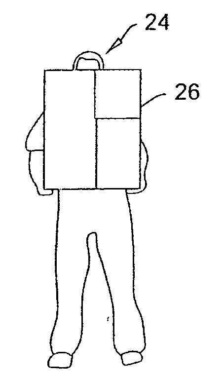
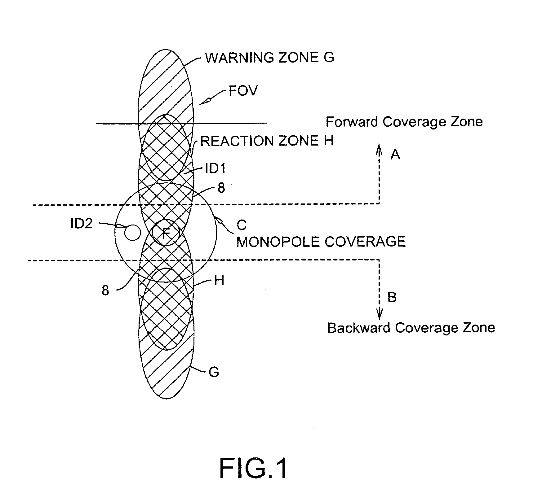
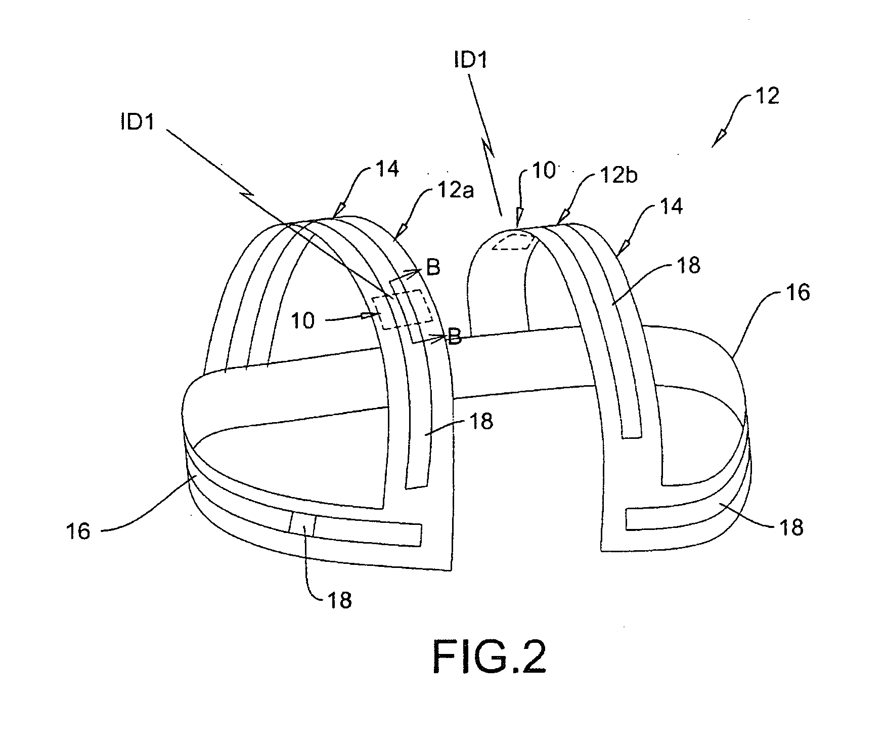
[0023]In the PSS example, the worker's RF sensor includes the antenna connected to a transceiver and a processor that communicates with the machine-mounted sensor via the transceiver and antenna. The machine mounted sensor monitors the paths that the machine, for example a forklift would take in the forward and backward directions, and therefore includes two directional antennas, namely a forward-looking and a rearward looking antenna. Only one of these antennas is activated at a time depending on the direction of movement. Each of the workers' sensors is given a unique identification (ID), so that the system is a full RFID wireless system. Moreover, many sensors with another set of IDs may be mounted on objects like walls or posts so that the machine may be programmed to react differently according to the set of IDs detected. Some machine types only require a single monopole antennae as per FIG. 18.

[0024]The PSS described by way of example herein inhibits accidents from happening i...


PUM


Abstract

An asset tracking system includes one or more RFID readers and one or more RFID tags cooperating with the readers, and at least one garment, wherein the readers each include an RF wideband transceiver and a linearly polarized antenna. Each reader polls periodically a corresponding one or more RFID tag to determine a distance of a particular tag from each reader. Each reader computes the tag's distance in real-time and updates a corresponding database in real-time for an on-demand reaction as determined by a processor in each reader. Each tag includes a wideband transceiver and an antenna array. The antenna array is implanted on each garment and ensures a spherical coverage around each tag. The antenna array includes two or more patch antenna distributed around each garment so as to provide full 360 degree and spherical coverage around each garment, and wherein each patch antenna is provided on a dielectric. Coverage is thereby provided by the patch antenna array and removes the need of having a single line of sight. Each tag may include an on-board processor adapted to adaptively switch between the antennas in the antenna array so as to select an appropriate antenna of the array for a signal from a corresponding reader.

Description

CROSS REFERENCE TO RELATED APPLICATION[0001]This application claims priority from U.S. Provisional Patent Application No. 61 / 193,730 filed Dec. 19, 2008 entitled System for Asset Tracking.FIELD OF THE INVENTION[0002]This invention relates to the field of radio frequency identification systems and in particular to a system for asset tracking using radio frequency identification and improved antenna adapted for use in safety systems.BACKGROUND OF THE INVENTION[0003]The system for asset tracking according to the present invention, including the improved antenna forming a part thereof, aims for example to assist in improving workers' safety in hazardous workplaces, when incorporated as part of for example a radio frequency identification (RFID) based personal safety system (PSS) such as described in U.S. patent application Ser. No. 11 / 822,911 and published under publication number US02008-0018472-A1 on Jan. 24, 2008, which provides one example of how aspects of the present invention may...

Claims


Application Information

Patent Timeline
Patent Type & Authority Applications(United States)
IPC IPC(8): H04Q5/22
CPCG06K7/0008G06K7/10079G06K19/041G06K19/07749G06K19/07786G06K2017/0045H04Q2209/47H01Q1/2216H01Q1/2225H01Q1/273H01Q3/24H01Q9/0407H04Q9/00G06K2017/0087
Inventor CHAMSEDDINE, AHMADSHERVEY, RICHARD CLAYTON
Owner PSST MOBILE EQUIP - RICHARD SHERVEY
Why Eureka
Try Eureka