Al technical title is built by PatSnap Al team. It summarizes the technical point description of the patent document.
a fluoroscopic imaging and dental technology, applied in the field of dental fluoroscopic imaging systems, can solve the problems of not being ergonomically placed by the dentist, and not being able to achieve the effect of reducing the risk of radiation to the patien
Active Publication Date: 2011-06-23
REAL TIME IMAGING TECH
View PDF48 Cites 35 Cited by
Summary
Abstract
Description
Claims
Application Information
AI Technical Summary
This helps you quickly interpret patents by identifying the three key elements:
Problems solved by technology
Method used
Benefits of technology
Problems solved by technology
The problem with all these existing dental digital intraoral and extraoral radiography technologies is that their final outcome is either 2D or a 3D still image.
The placement of the radiologist behind the screen resulted in significant radiation doses to the radiologist.
Despite these efforts, the image receptor configuration using the image intensifier and camera ...
Method used
Image
Click on the blue label to locate the original text in one second.
Reading with bidirectional positioning of images and text.
Examples
Embodiment Construction
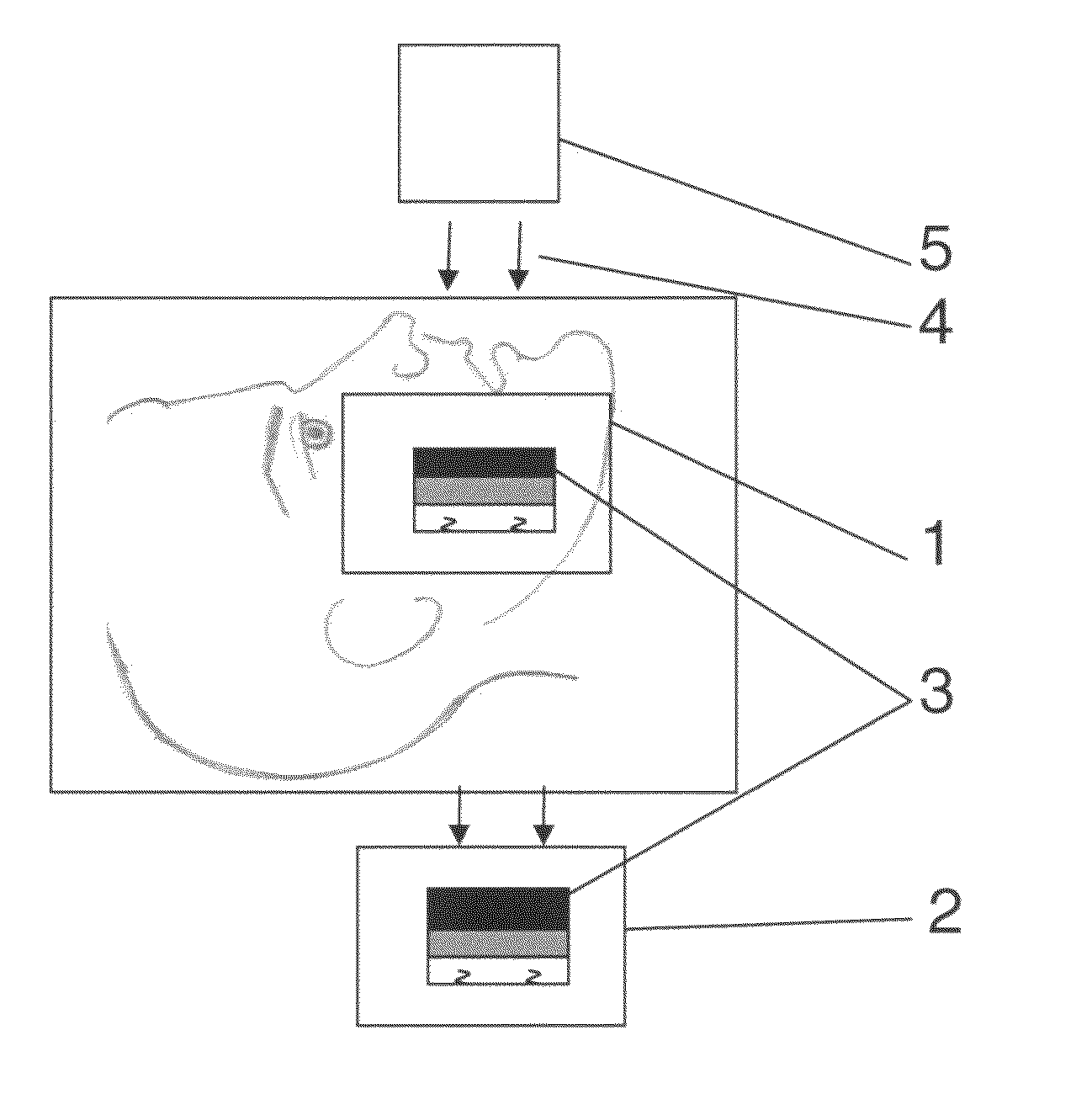
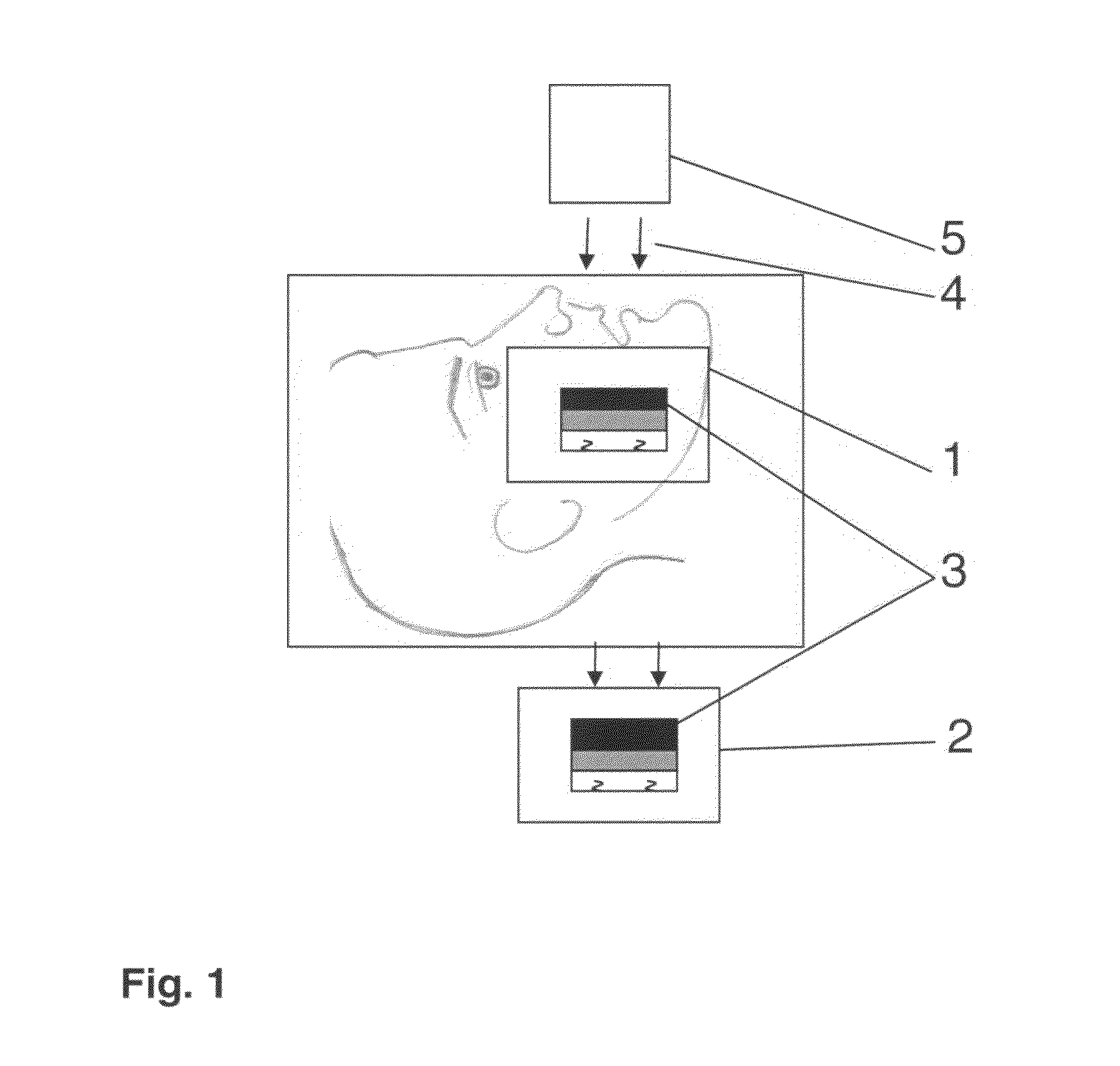
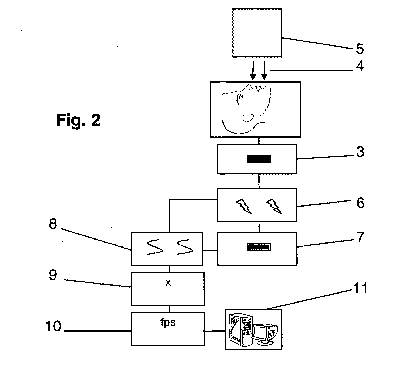
[0036]As described in FIGS. 1 and 2, this invention discloses a dental fluoroscopic imaging system comprised by an intraoral 1 and extraoral 2 flat panel detectors utilizing an x-ray converter 3 which includes a semiconductor of amorphous selenium (a-se), or a material such as NaI, NaI(TI), higher-Z bismuth germinate (BGO), BaF2, CaF2(Eu), high-purity germanium HPGe, Cesium Iodide (CsI), CsI(TI), CsI(Na), LaCl3(Ce), LaBr3(Ce), LuI3, Lu2SiO5, Gadolinium Oxysulphide (GSO), Lu1.8Y0.2SiO5(Ce), amorphous silicon (a-si), poly-si, metal ceramic, CdWO4, CaWO4, linear photodiode array (PDA), Si(Li), CdTe, CdZnTe, CZT, CdSe, CdS, Se, PbI2, PbTe, HgTe, HgI2, ZnS, ZnTe, ZnWO4, GaP, AlSb, YAG(Ce), Gd2O2S or Kodak Lanex in order to transform the low dose gamma rays or x-rays beam 4 received from a high frequency direct current (DC) emitter 5 after going through the dental examination area into electrical signals or a light image 6 consequent with the radiographed image. The emitter 5 may contain ...
PUM
Abstract
The dental fluoroscopic imaging system includes a flat panel detector comprised by a gamma-rays or x-rays converter, a plate, a collector, a processing unit and a transmitter suitable for 2D intraoral/extraoral and 3D extraoral dental fluoroscopy. The x-ray converter contains a material capable of transforming the low dose gamma rays or x-rays beam received from an emitter after going through the dental examination area into electrical signals or a light image consequent with the radiographed image. The plate transmits the electric signals or light image to a collector which amplifies it and sends it to a processing unit and then to transmitter designed to transfer digital images sequentially to a host computer and software which can acquire, process, transform, record, freeze and enhance 2D and 3D images of video frame rates. Two dimensional images are obtained while using a C-arm/U-arm configuration while 3D images are obtained while using the O-arm configuration.
Description
[0001]This Non-Provisional US patent application is based on the principles of the Provisional U.S. Patent Applications No. 61 / 201,744, 61 / 201,745, 61 / 201,746, 61 / 201,747 and 61 / 201,748 filled on Dec. 16, 2008.1. CROSS REFERENCES[0002]4,593,400June 1986Mouyen4,965,455October 1990Schneider5,049,987September 1991Hoppenstein5,262,649November 1993Antonuk et al.5,382,798January 1995Mouyen5,434,418July 1995Schick5,510,623April 1996Sayed et al.5,519,751May 1996Yamamoto et al.5,610,404March 1997Possin5,648,654July 1997Possin5,693,948December 1997Sayed et al.5,773,832June 1998Sayed et al.5,834,782November 1998Schick et al.5,841,830November 1998Barni et al.5,912,942June 1999Schick et al.5,949,848September 1999Giblom5,962,856October 1999Zhao et al.6,404,854June 2002Carrol et al.6,543,936April 2003Feldman6,566,809May 2003Fuchs et al.6,717,174April 2004Karellas7,016,461March 2006Rotondo et al.7,136,452November 2006Spartiotis et al.7,197,109March 2007Rotondo et al.7,211,817May 2007Moody7,231,014J...
Claims
Application Information
Patent Timeline
Application Date:The date an application was filed.
Publication Date:The date a patent or application was officially published.
First Publication Date:The earliest publication date of a patent with the same application number.
Issue Date:Publication date of the patent grant document.
PCT Entry Date:The Entry date of PCT National Phase.
Estimated Expiry Date:The statutory expiry date of a patent right according to the Patent Law, and it is the longest term of protection that the patent right can achieve without the termination of the patent right due to other reasons(Term extension factor has been taken into account ).
Invalid Date:Actual expiry date is based on effective date or publication date of legal transaction data of invalid patent.