
Superconducting Low Pass Filter for Quantum Computing and Method of Manufacturing the Same

a low-pass filter and superconducting technology, applied in the field of superconducting superconducting filter devices, can solve the problems of cryogenic systems, premature decoherence of systems, and methods that cannot meet the practical requirements of scalable quantum computers, and achieve high thermal conductivity

Active Publication Date: 2011-06-23
GLOBALFOUNDRIES US INC
View PDF6 Cites 28 Cited by
  • Summary
  • Abstract
  • Description
  • Claims
  • Application Information

AI Technical Summary

Benefits of technology

[0017]In another aspect of the invention, a superconducting low-pass filter for quantum computing devices includes a device including a plurality of containers defining cavities therein. The filter further includes input and output ports are connected to opposite ends of the device. The filter includes a plurality of coils of superconducting wire wherein one of the plurality of coils are positioned in each of the cavities of the containers, and each of the coils are electrically connected in the containers to one another and at least one coil is connected to the input port and at least one coil is connected to the output port. In the filter, a conductive polymer fills the cavities, and one or more covers are positioned over the containers for sealing the containers.
[0018]In a related aspect, each container is vacuumed sealed and degassed. Each cavity may further includes a solderable material. The containers may further include a superconducting metal. The containers may also include a material having high thermal conductivity. The wire coils may be impregnated with a mixture of ferromagnetic metal-powder filled epoxy.

Problems solved by technology

Current methods in the field of quantum computing perform quantum computations, however, the methods are not capable of meeting practical requirements of a scalable quantum computer.
The electronic noise must be fully suppressed, otherwise, the electronic noise can be transferred to the quantum system and lead to premature decoherence of the system.
In another aspect of current systems, another problem which occurs is that cryogenic systems (dewars (containers for holding, for example, liquid nitrogen), cryostats, dilution refrigerators, etc.) have limitations in both physical size and cooling power.
Thus, no active components (energy dissipating elements) can be located near the superconducting device being tested otherwise thermal dissipation negatively affects the experimental measurements.
However, these solutions have resulted in shortcomings because most cryostats are limited to just a few micro-watts of cooling power, thus, passive filters (RLC filter networks) near the experimental setup need to be limited in both size and number of elements due to their power dissipation.
Problems regarding quantum computing include determining the ultimate limits of computational speed and efficiency.
However, this is only possible if a superposition can be maintained by all of the qubits.
It is apparent that if decoherence times were the only criterion by which to design a quantum computer, then a long-lived qubit would be chosen, however, other criteria may limit the usefulness of a given qubit.
Another potential noise source is the superconducting circuit elements that are used to bias the qubit.
Because most passive circuit elements are dissipative (convert energy into heat), utilizing them in a low temperature measurement apparatus can be prohibitive if the thermal energy generated exceeds the cooling power of the low temperature refrigerator, typically less than 50 mW.
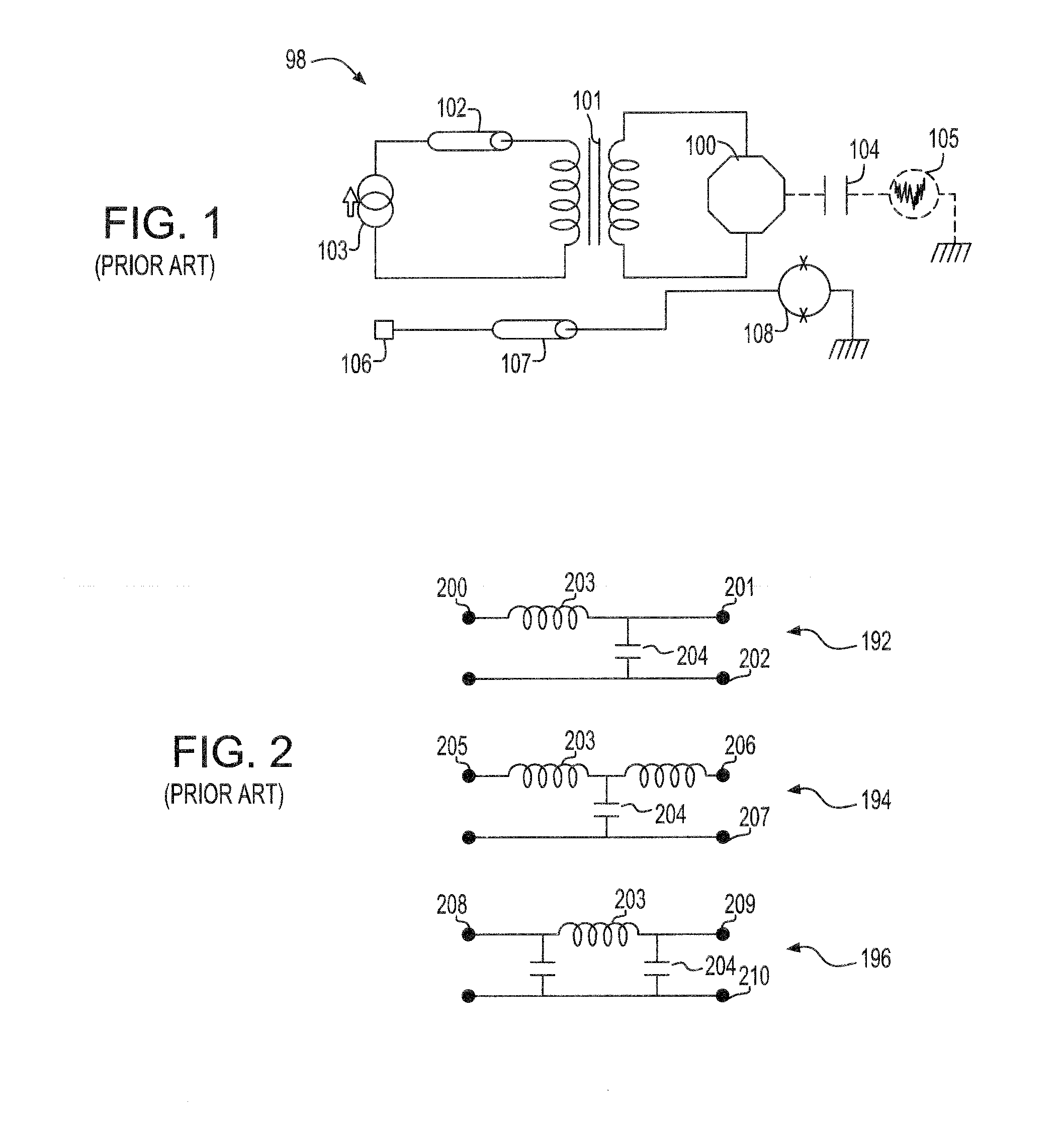
The filters described above typically require the use of many passive components (>5 components), and thus achieve the necessary filter requirements within the given thermal budget of the system can be impossible.
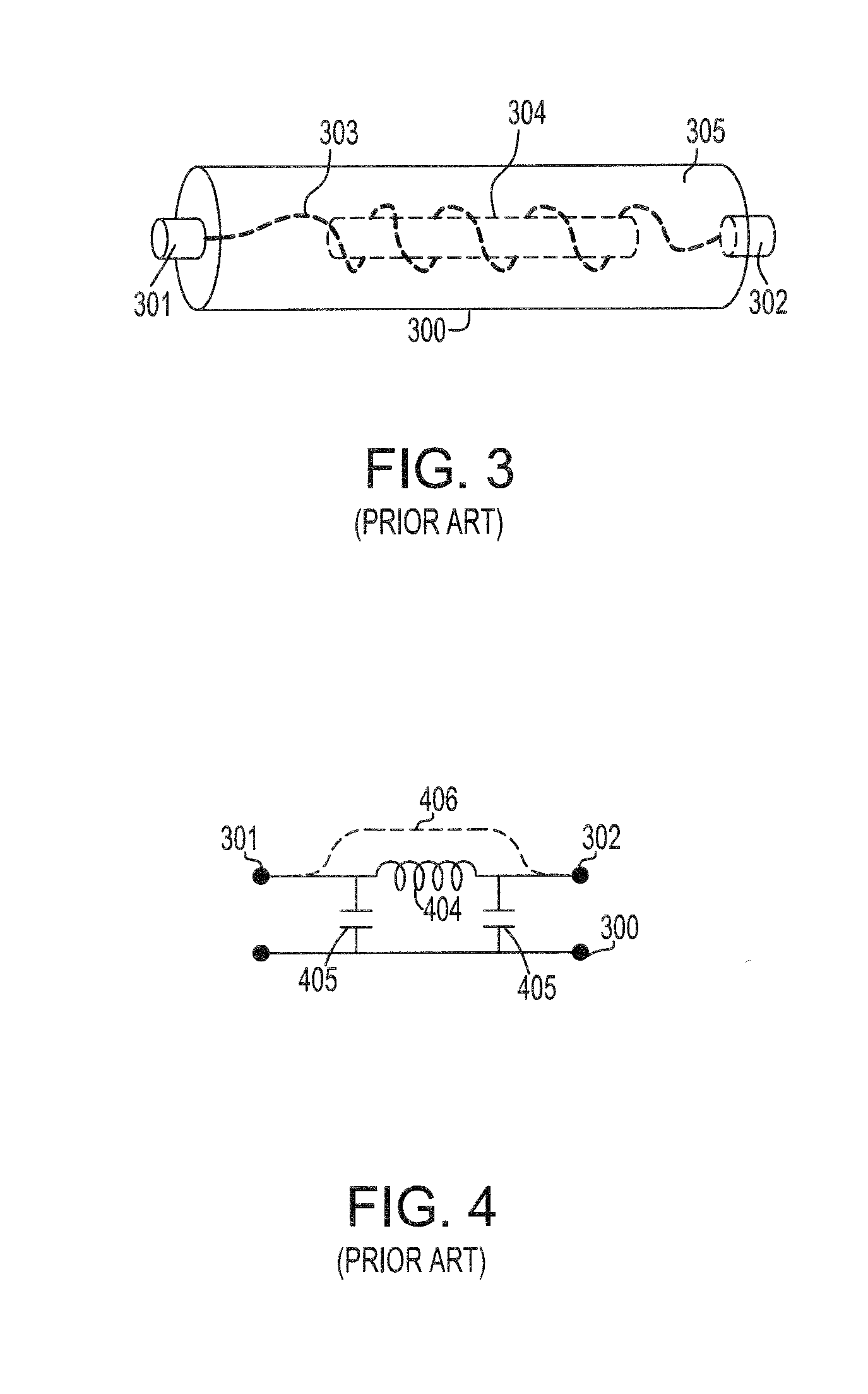
This additional parasitic capacitance can provide a pathway for high frequency noise to bypass the inductive element 404, thus leading to poor stop-band performance at gigahertz frequencies (109 Hz).

Method used


Image

  • Superconducting Low Pass Filter for Quantum Computing and Method of Manufacturing the Same
  • Superconducting Low Pass Filter for Quantum Computing and Method of Manufacturing the Same
  • Superconducting Low Pass Filter for Quantum Computing and Method of Manufacturing the Same

Examples


Embodiment Construction

[0030]In an illustrative embodiment of the present invention, an apparatus and method of constructing a low-pass filter is provided using superconductive wire coils and metallic powder and a conductive polymer inner filler, embodied as epoxy. Referring to FIGS. 5 and 6, includes a filter assembly 490 which includes containers 502 (or wells) on a support element 492, and a cover 501 extending over the containers 502. The container 502 provides an electrical ground. The filter 490 further includes an input port 500 and an output port 505 at opposite ends of the filter 490. The containers 502 include inductive elements 504, and are potted in the container 502 in a metal powder-filled medium 503. Connection leads 506 connect the input and output ports 500, 505, respectively to the inductive elements 504 and connect the inductive elements 504 to each other.

[0031]Because of the modular nature of the present invention, various configurations (linear, angled, area, etc.) of the filters can ...


PUM

PropertyMeasurementUnit
particle sizeaaaaaaaaaa
timeaaaaaaaaaa
diameteraaaaaaaaaa

Abstract

An apparatus and method for manufacturing a superconducting low-pass filter for quantum computing devices. The apparatus includes a plurality of containers and input and output ports connected to opposite ends of the apparatus. A plurality of coils of superconducting wire are wound using a mandrel. An adhesive is applied to the coils for maintaining a wound state. Each of the coils are positioned in each of the containers and electrically connected to each other with at least one coil being connected to the input port and at least one coil being connected to the output port. The coils are released or expanded from their wound state using an adhesive solvent. The containers are then filled with a conductive polymer and the containers are closed with one or more covers.

Description

BACKGROUND[0001]The present invention relates to fabrication of electronic filter devices for use with quantum computing devices, and more particularly, fabrication of low-pass electronic filter devices for use in cryogenic systems and quantum computing devices.[0002]Current methods in the field of quantum computing perform quantum computations, however, the methods are not capable of meeting practical requirements of a scalable quantum computer. Devices for quantum computers may be based on superconducting Josephson junction devices, or flux qubits. Josephson junction devices are based on the Josephson effect, which is the phenomenon of current flow across two weakly coupled supercomputers, separated by a very thin insulating barrier, this arrangement is known as a Josephson junction. The flux qubits include making measurements on superconducting qubit devices (cryogenic systems, high frequency electronics, etc.). A cryogenic system includes a vessel to hold a cryogen, typically he...

Claims


Application Information

Patent Timeline
Patent Type & Authority Applications(United States)
IPC IPC(8): H03H7/01H01L39/24H01P1/203H10N60/01
CPCB82Y10/00H03H1/00H03H7/0115H03H2001/0057H03H3/00Y10T29/49014H01L39/24H03H2001/0092Y10T29/49071H03H2001/005G06N99/002G06N10/00H10N60/01
Inventor FARINELLI, MATTHEWKEEFE, GEORGE A.MILLIKEN, JR., FRANKROZEN, JAMES R.
Owner GLOBALFOUNDRIES US INC
Learn More