[0004]An object of the exemplary embodiments and / or exemplary methods of the present invention is achieved by an aforementioned method having the features of the characterizing part by taking into account the severity of an error in assessing whether a faulty state, which is also referred to below as an error state, is to be regarded as an error and thus enables serious error states to be particularly quickly evaluated as errors. An error state is then evaluated or detected as an error if a limiting value is exceeded at least on average, taking into account the severity and duration of the error. The method according to the present invention thus makes it possible to detect an error both quickly and reliably.
[0007]According to the exemplary embodiments and / or exemplary methods of the present invention, a difference between an instantaneous value of the operating variable and a variable characterizing the limiting value is formed multiple times, for example periodically using or as a function of a
clock pulse of a control unit, synchronously using or as a function of a cyclical operation associated with the operating variable and / or as a function of a
signal which is generated, for example, with the aid of a functionality provided in the control unit. As a result, the method is applicable to continuously present and / or changing
operating variables, such as engine speeds, driving torques or fuel quantities, as well as to cyclically present
operating variables, for example,
injector activation times for
fuel injection into internal
combustion engines. The differences formed with the aid of the method are added to a sum, and the faulty state is evaluated as an error if the sum exceeds a predefinable threshold value. An integration of the formed differences is carried out thereby. In this way, temporary interruptions in the error state may essentially
delay the detection of the error only to the extent that the duration of a temporary interruption is relative to the presence of an error state.
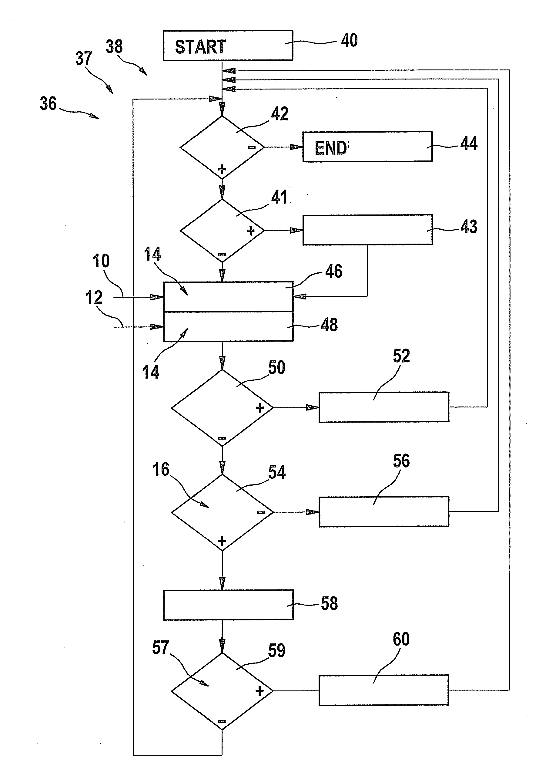
[0014]The method makes it possible, in particular, to also specify a debounce time, the faulty state being evaluated as an error upon expiration of the debounce time. If the debounce time is set as an “implicit” debounce time, the error is detected using the sum or the integral, as described above. If the debounce time is set as an “explicit” debounce time, this corresponds to a fixed debounce time, which is not influenced when the limiting value is exceeded. Detecting an error as a function of the expiration of the explicit debounce time may be carried out parallel to the error detection carried out as a function of the integration. For example, the operating variable may be compared with the limiting value provided for this operating variable, and the exceedance of the limiting value is used as a criterion for qualifying the error state as an error without this taking into account the amount by which the limiting value is exceeded. In this way, even very slight exceedances may be quickly evaluated as errors if the exceedance is present without interruption during the course of the debounce time. The explicit specification of a debounce time further increases the reliability of the method and makes it possible to easily take into account, for example, specific conditions which require an explicit debounce time to be taken into account.
[0017]One embodiment of the method provides that a variable characterizing the operating variable is added to a counter content, and a variable characterizing the limiting value is subtracted from the counter content. In this way, a counter which is implemented, for example, with the aid of a
computer program as the
integrator, may be advantageously used for error detection. An instantaneous counter content in this case corresponds to the sum or to an integral. In each case, the desired resolution or precision as well as a possible value range for the threshold value may be advantageously determined by the counter variable. Due to the addition and subtraction operations, it is not necessary to form the difference between the operating variable and the limiting value separately. A specific implementation may be carried out, for example, by one or more memory cells (bytes) of a
random access memory (RAM) or with the aid of a special register within the control unit. A memory of this type is frequently already provided in a control unit, so that no additional costs are incurred.
[0018]In addition, it is proposed that a constant is also continuously added to the sum when the operating variable exceeds the limiting value. As a result, possible specific conditions may be met which, if necessary, specify fast error detection in cases in which a provided limiting value is only slightly exceeded. For example, 40% of a product of the operating variable multiplied by a sampling period may be added to the sum in addition to the difference between the operating variable and the limiting value in each addition step. This makes it possible to use the method with particular flexibility.
[0019]A further embodiment of the present invention provides that the sum is limited to the
lower threshold value if the sum falls below a
lower threshold value. For example, this
lower threshold value is zero. This makes it possible to reliably prevent the sum or the integral from assuming large negative values during a longer phase in which the operating variable does not exceed the limiting value. The limitation to the lower threshold value also achieves the fact that the sum is formed starting at a defined initial state each time the limiting value is first exceeded.

