Method and device for determining and balancing the working point of valves in a hydraulic system

a technology of hydraulic system and working point, which is applied in the direction of water supply installation, braking system, instruments, etc., can solve the problems of critical situations in vehicle dynamics, vehicle oversteering behavior, and vehicle tending to become unstable, so as to reduce the pressure rise, accurate over-energizing of the closed valve, and the effect of power dissipation

Inactive Publication Date: 2011-06-23
ROBERT BOSCH GMBH
View PDF15 Cites 6 Cited by
  • Summary
  • Abstract
  • Description
  • Claims
  • Application Information

AI Technical Summary

Benefits of technology

[0022]If the pressure sensor is mounted on one circuit, the friction of the main cylinder piston should be taken into account for calculating the pressure in the other circuit. The inlet valve or valves of the lower-pressure circuit (i.e. the circuit that is measured first) may close before the switchover valve of the higher-pressure circuit opens, so that the circuit volume does not reduce the pressure rise in the circuit that is to be measured.
[0023]The method moreover exhibits the further advantages that no additional external sensors are required. The performance of

Problems solved by technology

With an X-split, different behavior by the two brake circuits can result in critical situations in terms of vehicle dynamics.
In the case of DWT-B, for example, if the right rear wheel is braked in a right-hand curve, this deliberately causes an oversteer tendency in the vehicle's behavior.
If too much pressure is then established because of the random tolerance

Method used


Image

  • Method and device for determining and balancing the working point of valves in a hydraulic system
  • Method and device for determining and balancing the working point of valves in a hydraulic system
  • Method and device for determining and balancing the working point of valves in a hydraulic system

Examples


Embodiment Construction

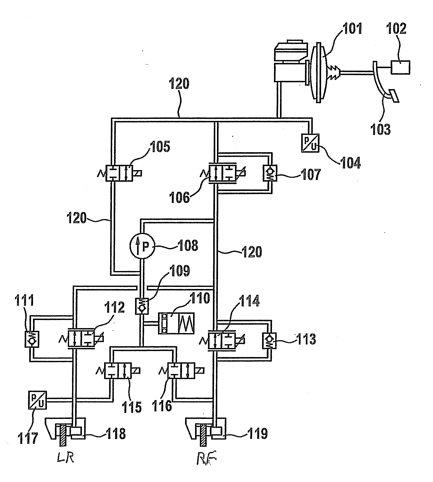
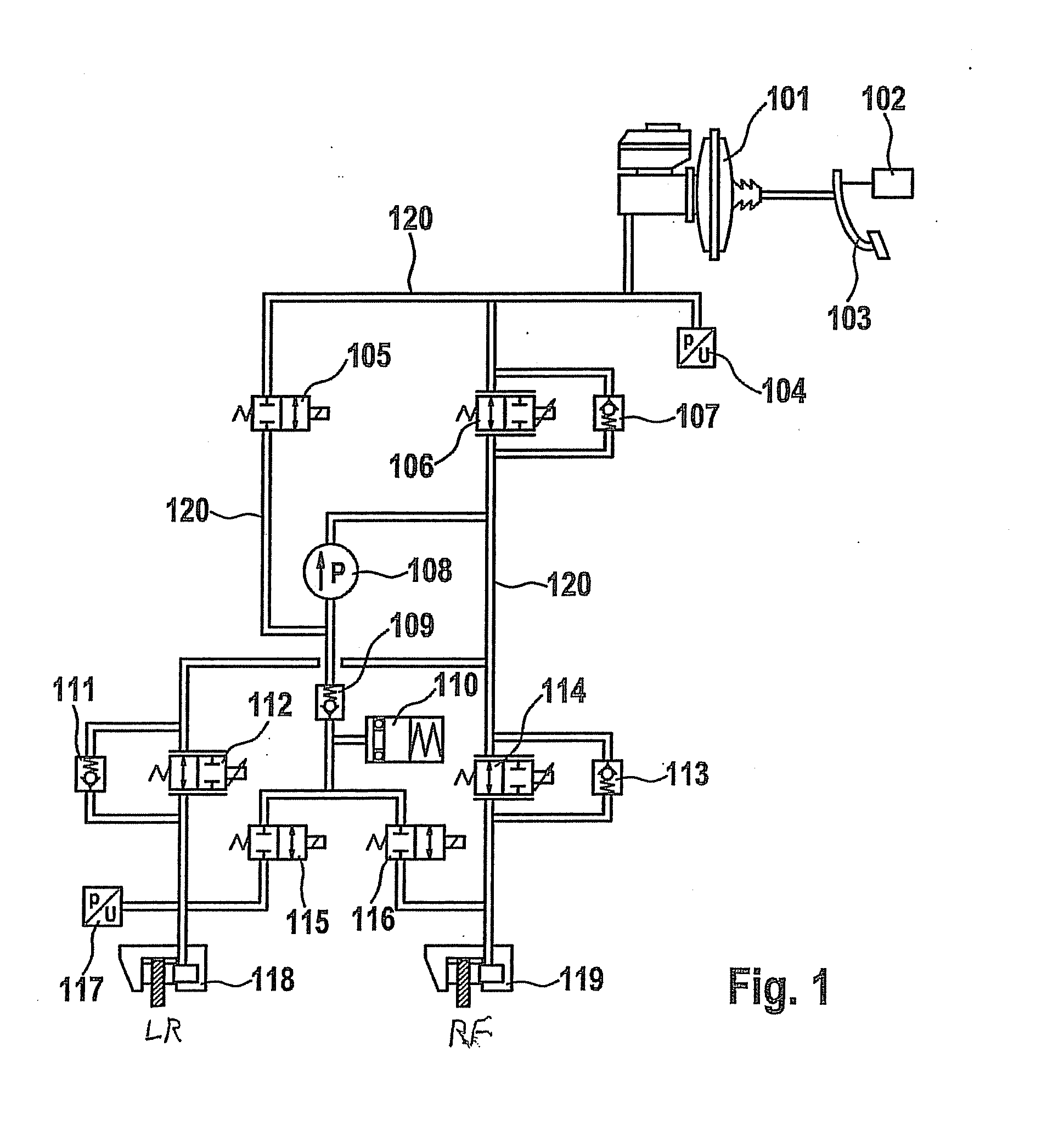
[0033]FIG. 1 is a block diagram of a hydraulic brake system of a vehicle in which the hydraulic brake system is split in known fashion into two circuits, only the first circuit being depicted here. The circuit serves to actuate the brakes of the left rear wheel LR and right front wheel RF of the vehicle. In the present case, a vehicle having four wheels is assumed. If more than four wheels are present, they either can be referred to the double-circuit braking system as illustrated in FIG. 1, or more than two independent brake circuits can be present. The hydraulic system is connected to a double-circuit main brake cylinder 101 that encompasses one or two independent master cylinders that can be actuated by a brake pedal 103. Brake pedal 103 additionally applies control to a brake light switch 102. The mutually independent brake cylinders are described below using the example of the first brake circuit, the second brake cylinder being of identical construction.

[0034]The first brake c...


PUM


Abstract

A method and an apparatus for ascertaining the working point of switchover valves of a hydraulic system of a vehicle, in particular of a hydraulic brake circuit, are described in which the hydraulic system contains at least a pressure generating arrangement, a high-pressure switching valve, a switchover valve, and an admission pressure sensor, an admission pressure that is higher than the target pressure of the switchover valve being established, the switchover valve being energized with a target current corresponding to the target pressure, admission pressure being reduced until the switchover valve closes, with the switchover valve closed, a nominal admission pressure being established as an admission pressure, after the switchover valve opens, a pressure difference Δp between admission pressure and a circuit pressure being sensed, and on the basis of the pressure difference Δp, the working point being ascertained.

Description

FIELD OF THE INVENTION[0001]The present invention relates to a method for ascertaining and equalizing the working point of switchover valves or circuit pressure valves in a hydraulic system, and to a control unit for carrying out such a method. The present invention further relates to a program for execution by a data processing system that carries out the method, and to a data medium having the stored program for execution by a data processing system.BACKGROUND INFORMATION[0002]Increasing numbers of vehicles are being equipped with additional active and passive safety systems, not prescribed by legislation, in order on the one hand to prevent accidents and on the other hand to minimize the consequences of accidents. Such safety systems include, for example, an electronic stability program (ESP) in which, by controlled braking interventions at the wheels of a vehicle, unintentional understeer or oversteer, and therefore vehicle breakaway, are counteracted. In addition to this standa...

Claims


Application Information

Patent Timeline
IPC IPC(8): B60T8/26F16K31/00
CPCB60T8/36B60T8/4872B60T8/3655Y10T137/0379Y10T137/7758B60T8/48B60T13/68
Inventor MAHLENBREY, ULRICH
Owner ROBERT BOSCH GMBH
Why Eureka
Try Eureka