Combined power transmission and drive unit for use in hybrid systems and a hybrid system

Active Publication Date: 2011-06-30
SCHAEFFLER TECH AG & CO KG
View PDF5 Cites 28 Cited by
  • Summary
  • Abstract
  • Description
  • Claims
  • Application Information

AI Technical Summary

Benefits of technology

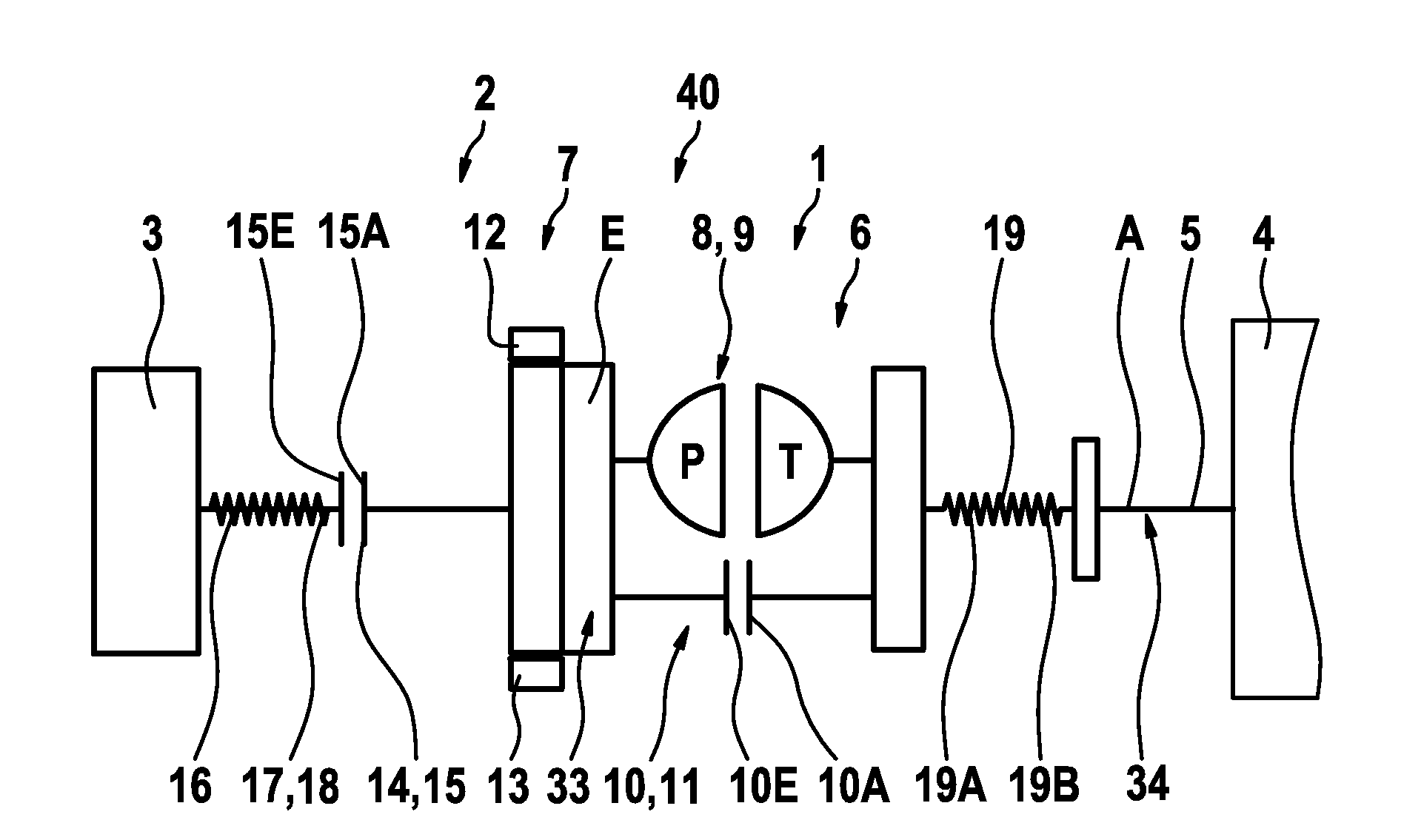
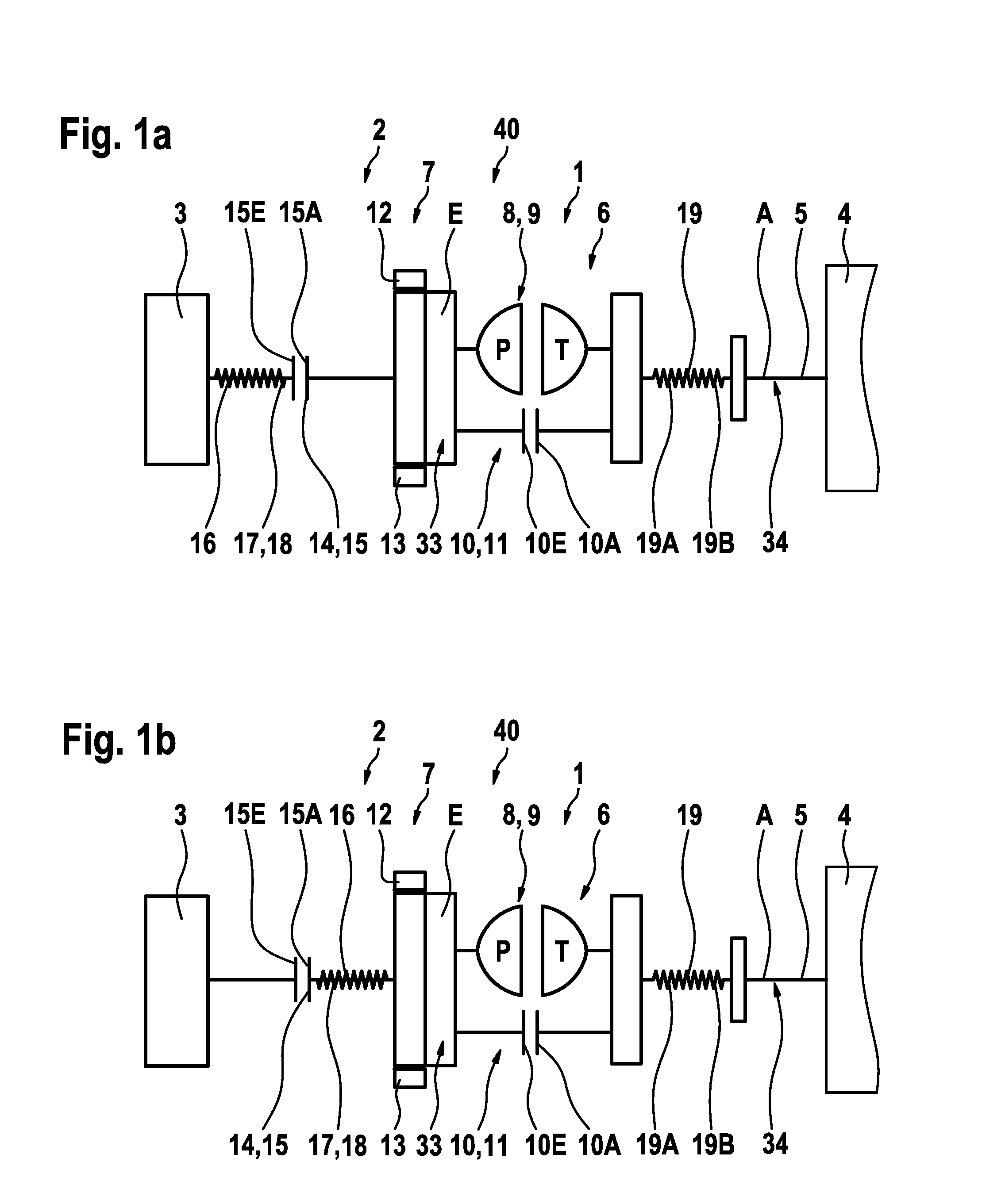
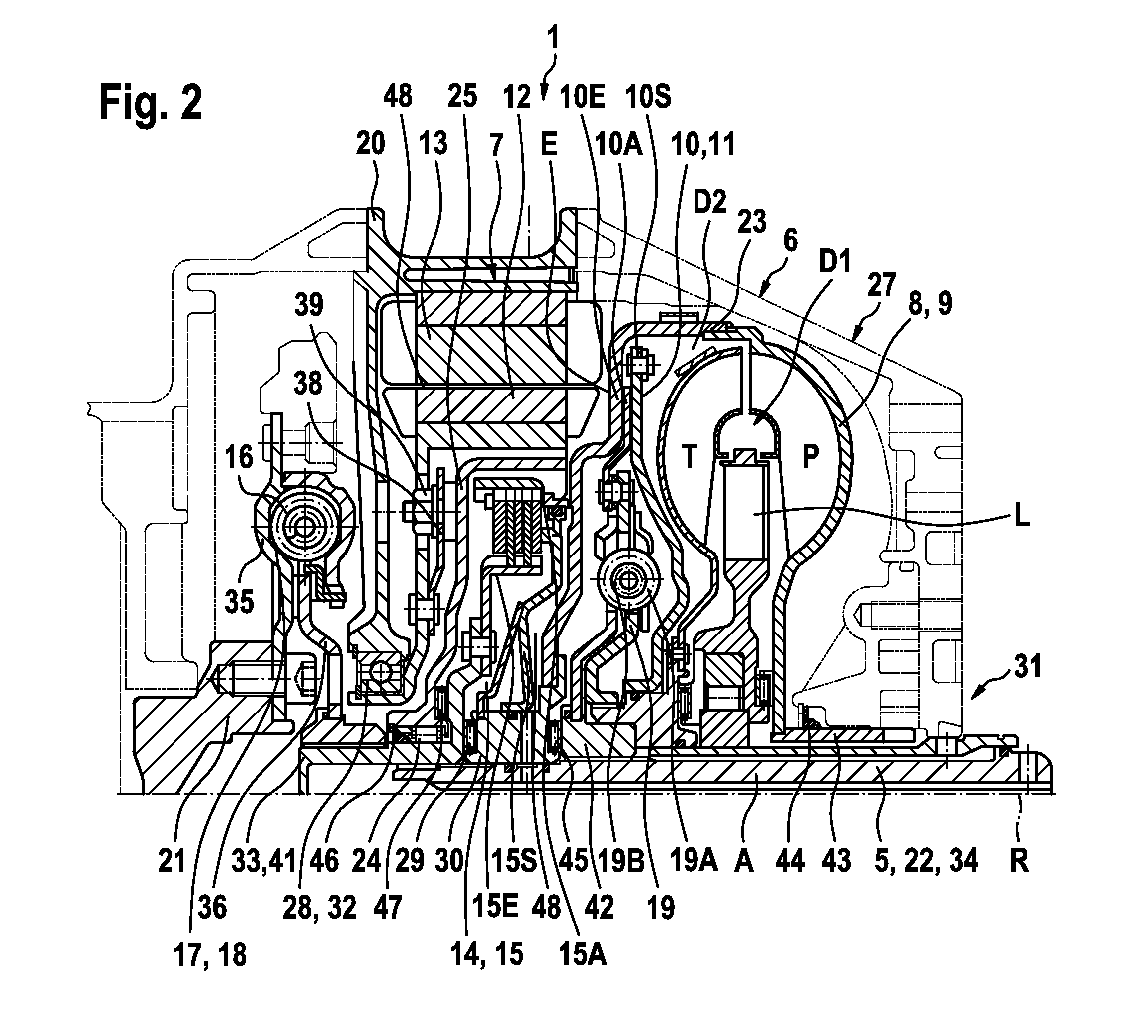
[0006]The electric machine is executed as a dry-running electric machine. This permits expansion of the application spectrum and furthermore reduction of the required sealing functions. The advantage is that the combined power transmission and drive unit can be mounted in a simple manner, in that the assembly entails durable preassembled units that are prefabricated and kept in stock. These units can be tested separately in advance and therefore error analysis and remedy can occur directly on an individual assembly unit. The preassembled units thereby are disposed next to one another essentially in axial direction, connected together by simply attaching or stringing them on the transmission input shaft in a force-closed manner, a form-closed manner, or in combinations thereof. A screw-connection is

Problems solved by technology

Nevertheless, the assembly can be relatively complex in design.
A further disadvantage is that the power transmission device and the switchable clutch device constitute devices, which during operation are surrounded by a service fluid or which require a service fluid to realize the mode of operation such that individual components are always covered with the service fluid or rotate in the fluid.
Based on the depicted arrangement such that the electric machine is exposed to the service

Method used


Image

  • Combined power transmission and drive unit for use in hybrid systems and a hybrid system
  • Combined power transmission and drive unit for use in hybrid systems and a hybrid system
  • Combined power transmission and drive unit for use in hybrid systems and a hybrid system

Examples


Embodiment Construction

[0039]At the outset, it should be appreciated that like drawing numbers on different drawing views identify identical, or functionally similar, structural elements of the invention. While the present invention is described with respect to what is presently considered to be the preferred aspects, it is to be understood that the invention as claimed is not limited to the disclosed aspects.

[0040]Furthermore, it is understood that this invention is not limited to the particular methodology, materials and modifications described and, as such, may, of course, vary. It is also understood that the terminology used herein is for the purpose of describing particular aspects only, and is not intended to limit the scope of the present invention, which is limited only by the appended claims.

[0041]Unless defined otherwise, all technical and scientific terms used herein have the same meaning as commonly understood to one of ordinary skill in the art to which this invention belongs.

[0042]Adverting ...


PUM


Abstract

A combined power transmission and drive unit for use in hybrid systems between a first engine and a transmission device, broadly including at least an input connectable with the engine, a power transmission device by which the output is connected with a transmission input shaft, a device for selectively at least interrupting/establishing the power flow to the input of the power transmission device and an electric machine including at least one rotor that is connected non-rotatably with the input of the power transmission device. Furthermore, the invention relates to a hybrid system, including a first engine and a combined power transmission and drive unit connected downstream of the engine.

Description

CROSS-REFERENCE TO RELATED APPLICATIONS[0001]This application is the National Stage of PCT International Application No. PCT / DE2009 / 000658, filed May 11, 2009, which application published in German and is hereby incorporated by reference in its entirety, which application claims priority from German Patent Application No. DE 10 2008 026 423.7, filed Jun. 2, 2008, which is incorporated by reference in its entirety.FIELD OF THE INVENTION[0002]The invention relates to a combined power transmission and drive unit for use in hybrid systems between a first engine and a transmission device, for example, a transmission device including at least an input connectable with the engine, a power transmission device by which the output is connected with a transmission input shaft, a device for selectively at least interrupting / establishing the power flow to the input of the power transmission device and an electric machine including at least one rotor that is connected non-rotatably with the input...

Claims


Application Information

Patent Timeline
IPC IPC(8): B60K6/36F16H37/06
CPCB60K6/40B60K6/405B60K6/48F16H2045/0205F16H2045/021Y10T477/23F16H2045/0278F16H2045/0284Y02T10/6221Y10T477/30Y10T74/19051F16H2045/0252Y02T10/62
Inventor MUELLER, BRUNO
Owner SCHAEFFLER TECH AG & CO KG
Why Eureka
Try Eureka