Gate valve unit, substrate processing device and substrate processing method thereof

a technology of substrate processing and gate valve, which is applied in the direction of lighting and heating apparatus, charge manipulation, furnaces, etc., can solve the problems of deteriorating sealing function, affecting the effect of sealing function, and unable to maintain the target vacuum degree, so as to reduce the sealing function, prevent the effect of deteriorating function

Active Publication Date: 2014-01-02
TOKYO ELECTRON LTD
View PDF5 Cites 37 Cited by
  • Summary
  • Abstract
  • Description
  • Claims
  • Application Information

AI Technical Summary

Benefits of technology

[0019]According to one embodiment of the present invention, when one chamber required to maintain the high vacuum degree is depressurized, the substrate transferring port of the one chamber is closed by a valve body. At this time, a substrate transferring port of the other chamber communicates with a gate valve unit in state of being open. Due to this, although first and second sealing members are heated due to heat from a hot wall chamber to thereby reduce a sealing function and allow air to penetrate, the air enters the interior of the gate valve unit from communicate holes and flows from the substrate transferring port to the other chamber so as to be exhausted by the other chamber. As a result, since the air, which enters the interior of the other chamber by passing through the outer second sealing member, can be prevented from entering the interior of the one chamber required to maintain the high vacuum degree, the pressure in the one chamber can be presented from increasing and the predetermined vacuum pressure can be maintained.
[0020]As described above, as a gap between the first sealing member and the second sealing member is vacuum-evacuated by the other chamber, the air can be effectively prevented from entering the interior of the one chamber required to maintain the high vacuum degree by passing through the first sealing member although the air passes through, for example, the outer second sealing member.
[0021]According to one embodiment of the present invention, although, for example, processing gas supplied for processing the substrate in the hot wall chamber enters the interior of the gate valve unit from the substrate transferring port of the chamber, the processing gas can be prevented from being adhered to the surface of a bellows. Thus, the generation of particles can be prevented.
[0022]Accordingly, since the communicate holes are not clogged by a valve body restriction member, the air can be effectively exhausted from the communicate holes towards the process chamber.
[0023]According to one embodiment of the present invention, when the transfer chamber required to maintain the high vacuum degree is depressurized, the substrate transferring port of the transfer chamber is closed by the valve body. At this time, the substrate transferring port of the hot wall chamber communicates with the gate valve unit in a state of being open. Due to this, although the first and second sealing members are heated due to the heat from the hot wall chamber to thereby reduce a sealing function and allow air to penetrate, the air enters the interior of the gate valve unit from communicate holes and flows from the substrate transferring port to the hot wall chamber so as to be exhausted by the hot wall chamber. As a result, since the air, which enters the interior of the hot wall chamber by passing through the outer second sealing member, can be prevented from entering the interior of the transfer chamber required to maintain the high vacuum degree, the pressure in the transfer chamber can be presented from increasing and the predetermined vacuum pressure can be maintained.
[0024]According to one embodiment of the present invention, with regard to the gate valve unit provided between the high vacuum hot wall chamber and the transfer chamber when the high vacuum hot wall chamber is connected to the transfer chamber, as the gate valve unit is configured as described above, when the chamber required to maintain the high vacuum degree is depressurized, the substrate transferring port of the chamber is closed by the valve body. At this time, the substrate transferring port of the other chamber communicates with the gate valve unit in a state of being open. Due to this, although the first and second sealing members are heated due to the heat from the hot wall chamber to thereby reduce a sealing function and allow air to penetrate, the air enters the interior of the gate valve unit from the communicate holes and flows from the substrate transferring port to the other chamber so as to be exhausted by the other chamber. As a result, since the air, which enters the interior of the other chamber by passing through the outer second sealing member, can be prevented from entering the interior of the chamber required to maintain the high vacuum degree, the pressure in the chamber can be presented from increasing and the predetermined vacuum pressure can be maintained.

Problems solved by technology

However, since the sealing member provided in the gate valve unit is composed of, e.g., an O-ring made of fluorine-based resin, a sealing function is deteriorated when the sealing member is heated, which allows air to penetrate.
In that case, since the heat of the sidewall is transmitted to the gate valve unit, even the sealing member of the transfer chamber as well as the sealing member of the process chamber is heated, which deteriorates the sealing function.
Like this, if the sealing member allows air to penetrate, the air enters the interior of the chamber through the substrate transferring port to increase pressure in the chamber, which causes such a problem that a target degree of vacuum cannot be maintained.
Furthermore, when a temperature of the O-ring heated at pressure lower than a 10−7 Torr order exceeds room temperature, the pressure in the chamber may not be maintained even at a relatively low temperature equal to or less than 100° C.
Although the double sealing members are applied to the process chamber, a sealing function thereof is deteriorated, thereby still failing to prevent air from entering the interior of a transfer chamber.

Method used


Image

  • Gate valve unit, substrate processing device and substrate processing method thereof
  • Gate valve unit, substrate processing device and substrate processing method thereof
  • Gate valve unit, substrate processing device and substrate processing method thereof

Examples


Embodiment Construction

[0044]Hereinafter, preferred embodiments of the present invention will now be described in detail with reference to the accompanying drawings. Throughout the specification and the drawings, the elements having substantially the same functions and configurations are denoted by the same reference numerals, and thus explanation of which is not repeated. Also, 1 Torr in the specification refers to 101325 / 760 Pa.

[0045](A Configuration Example of a Substrate Processing Device)

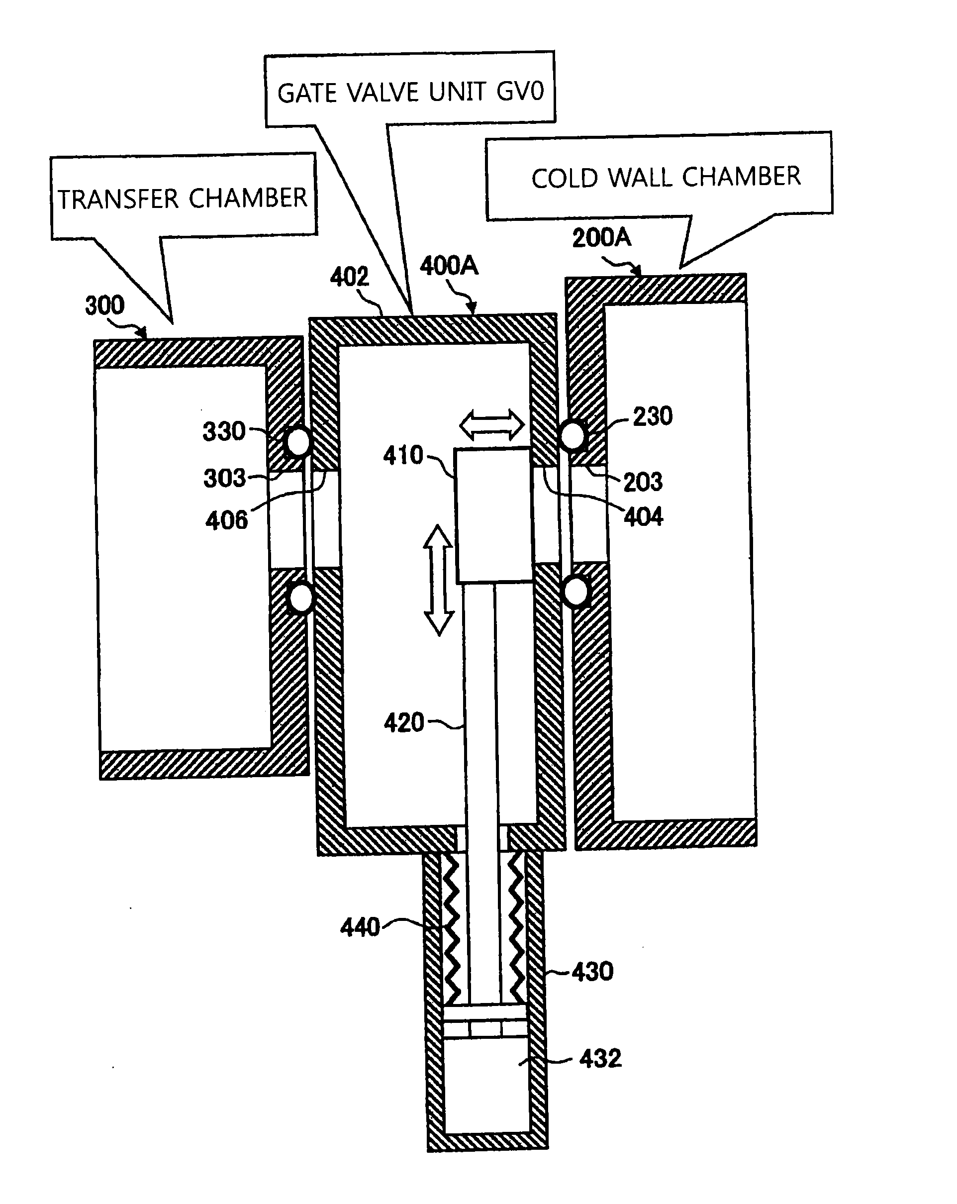
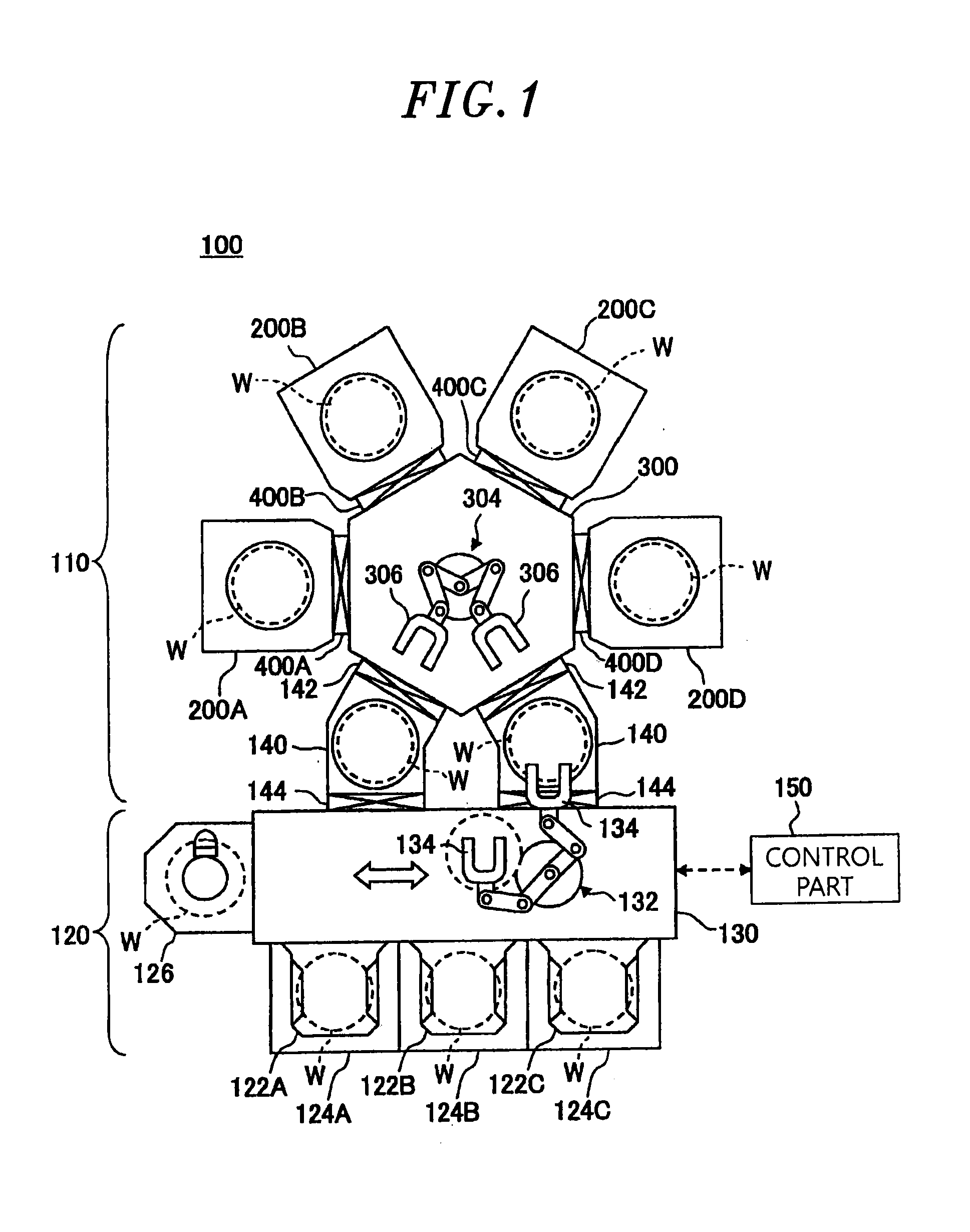
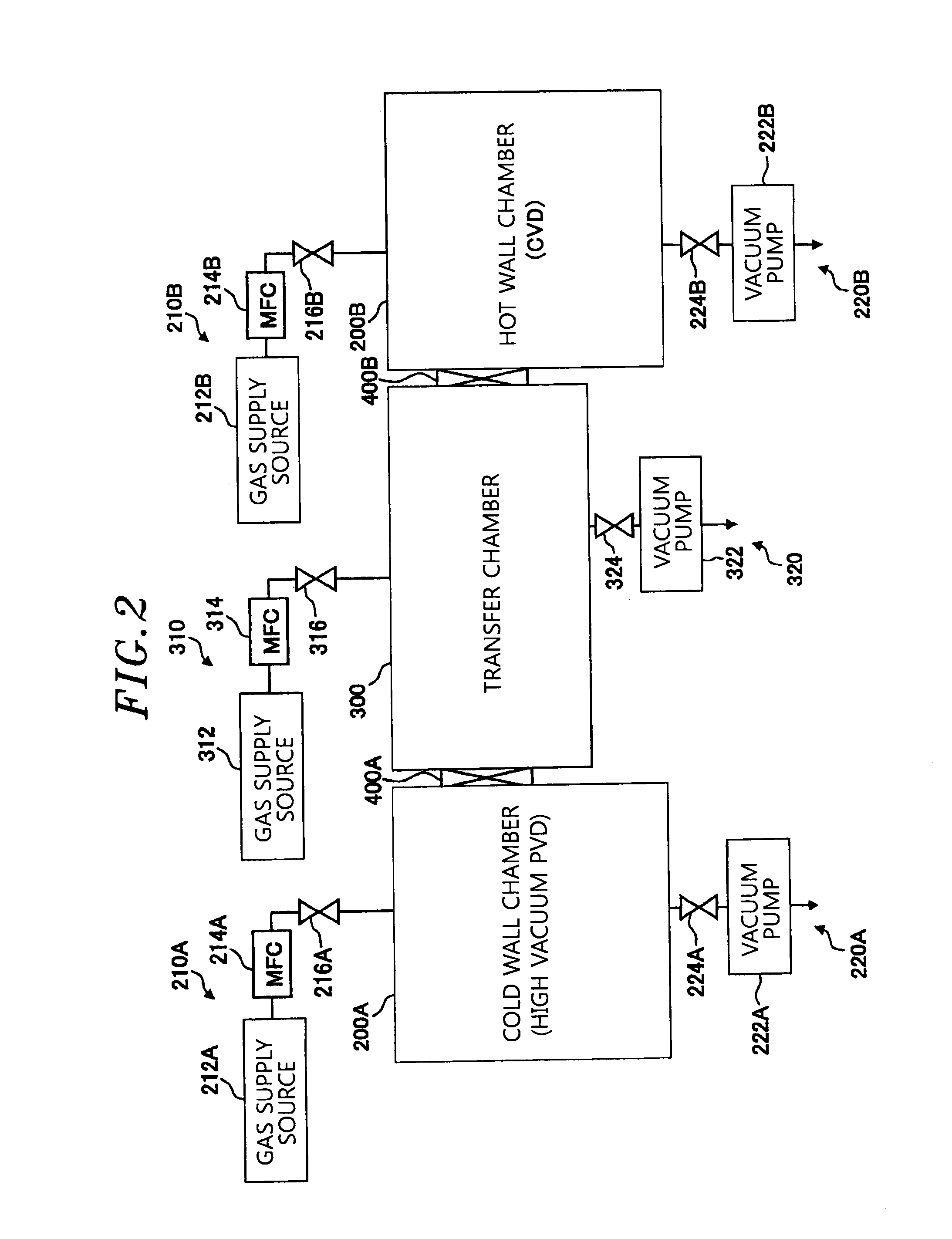
[0046]First, a configuration example of a substrate processing device according to an embodiment of the present invention to which a gate valve unit can be applied will be described with reference to the drawings. FIG. 1 is a cross-sectional view showing a schematic configuration of the substrate processing device according to the embodiment. The substrate processing device 100 shown in FIG. 1 includes: a process module 110 (a vacuum processing unit) in which a plurality of process chambers 200A to 200D (for example,...


PUM

PropertyMeasurementUnit
pressureaaaaaaaaaa
temperatureaaaaaaaaaa
pressureaaaaaaaaaa

Abstract

A substrate processing device includes a depressurizable hot wall chamber having a sidewall with a temperature which becomes higher than room temperature and a first substrate transferring port provided in the sidewall, a depressurizable transfer chamber having a transfer arm mechanism and a second substrate transferring port, and a gate valve unit provided between the hot wall chamber and the transfer chamber. The gate valve unit includes: a housing having a sidewall provided with communicating holes, a first housing substrate transferring port, and a second housing substrate transferring port; a valve body which is elevatable in the housing; and a double sealing structure having a first sealing member and a second sealing member provided at an outer side of the first sealing member. The communicating holes communicate a gap between the first sealing member and the second sealing member with an internal space of the housing.

Description

FIELD OF THE INVENTION[0001]The present invention relates to a gate valve unit provided between a processing chamber and a transfer chamber configured to perform a processing process for a substrate such as a semiconductor wafer, a liquid crystal substrate, a solar cell panel substrate or the like, a substrate process device including the gate valve unit, and a substrate processing method thereof.BACKGROUND OF THE INVENTION[0002]In a manufacture process of a semiconductor apparatus, there is a need to transfer a substrate such as a semiconductor wafer or the like between chambers having pressure atmospheres with different vacuum degrees. The transferring of the substrate is performed through substrate transferring ports provided in sidewalls of the chambers after pressure is adjusted so as to reduce a difference in pressure among the respective chambers. In order to hermetically seal the substrate transferring ports before and after the transferring of the substrate, a gate valve un...

Claims


Application Information

Patent Timeline
Patent Type & Authority Applications(United States)
IPC IPC(8): F16K3/30B65G49/00
CPCF16K3/30B65G49/00F16K51/02H01L21/67126C23C16/4401H01L21/28556H01L21/76841F16K3/0227C23C14/566C23C16/16F16K3/182C23C16/54
Inventor YAMAMOTO, KAORUHARA, MASAMICHIMIYASHITA, TETSUYA
Owner TOKYO ELECTRON LTD
Why Eureka
Try Eureka