Gas-cluster-jet generator and gas-cluster ion-beam apparatus utilizing an improved gas-cluster-jet generator

a gas-cluster-jet and generator technology, applied in the field of cluster jet formation, can solve the problem of shallow effect upon striking the surfa

Active Publication Date: 2011-06-30
EXOGENESIS CORP
View PDF17 Cites 24 Cited by
  • Summary
  • Abstract
  • Description
  • Claims
  • Application Information

AI Technical Summary

Benefits of technology

[0013]The present invention provides a gas-cluster-jet generator with improved vacuum management techniques and apparatus. The gas-cluster-jet generator comprises a substantially conical shaped vacuum chamber for housing the nozzle and skimmer portions of the gas-cluster-jet generator. The skimmer may be located at the narrow end of the conical chamber and a close-coupled vacuum pump is located at the wide end of the conical chamber so that skimmed gases are evacuated in a direction opposite to the flow direction of the gas-cluster jet. Support members for the nozzle are high vacuum conductivity “spider” supports that provide support rigidity while minimizing gas flow obstruction for high pumping speed. The nozzle and skimmer may have precision, fixed relative alignment, or may optionally have an adjustable nozzle aiming capability for aligning the gas-cluster-jet with the skimmer.
[0018]The gas expansion nozzle may be mounted at opposing input and outlet ends using a limited number of elongated members extending from sides of the chamber to allow easy flow of gas molecules and clusters that are not part of the beam in the opposing predetermined direction. The gas expansion nozzle may be adjustably mounted at the outlet end of the nozzle to enable adjustment of the predetermined direction. The gas expansion nozzle may be tiltably mounted at the input end of the nozzle to support adjustment of the predetermined direction at the outlet end of the nozzle.

Problems solved by technology

Additionally, a large quantity of un-clustered gas atoms / molecules may also flow into the vacuum through the nozzle.
However, because of the large number of atoms or molecules in each gas-cluster ion, and because of the loose binding of the clusters, their effect upon striking a surface is very shallow—the cluster is disrupted at impact and each atom or molecule carries only a few eV of energy.

Method used


Image

  • Gas-cluster-jet generator and gas-cluster ion-beam apparatus utilizing an improved gas-cluster-jet generator
  • Gas-cluster-jet generator and gas-cluster ion-beam apparatus utilizing an improved gas-cluster-jet generator
  • Gas-cluster-jet generator and gas-cluster ion-beam apparatus utilizing an improved gas-cluster-jet generator

Examples


first embodiment

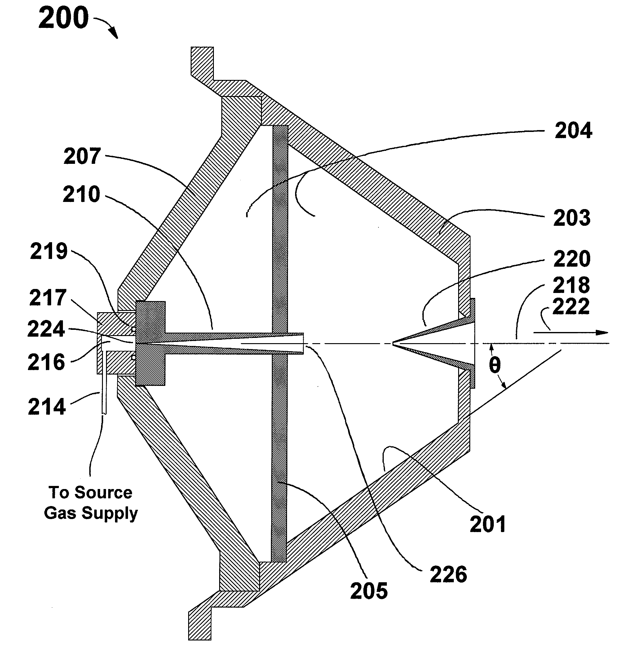
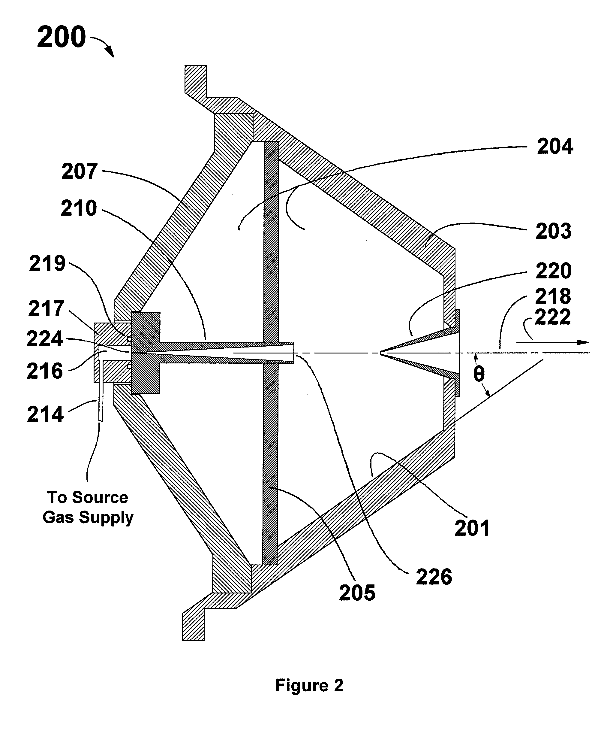
[0047]FIG. 2 is a cross-sectional view 200 of a portion of an improved gas-cluster-jet generator according to the invention. A conical gas-cluster-jet generator chamber enclosure 203 encloses a gas-cluster-jet generator chamber 204. The conical gas-cluster-jet generator chamber enclosure 203 is substantially conical and has an inner surface 201 that is conically coaxial with gas-cluster-jet trajectory 218. Gas-cluster-jet trajectory 218 has a flow direction 222. The inner surface 201 forms a circular cone with conical half-angle θ, with respect to gas-cluster-jet trajectory 218. The conical half-angle θ may be in the range of from about 30 degrees to about 50 degrees dependent on other geometrical considerations of the application, but it is preferably about 35 degrees. First nozzle support spider 205 and second nozzle support spider 207 support the nozzle 210. A high-pressure source gas is delivered to the nozzle 210 through a flexible gas feed tube 214 and gas flange 217, attached...

second embodiment

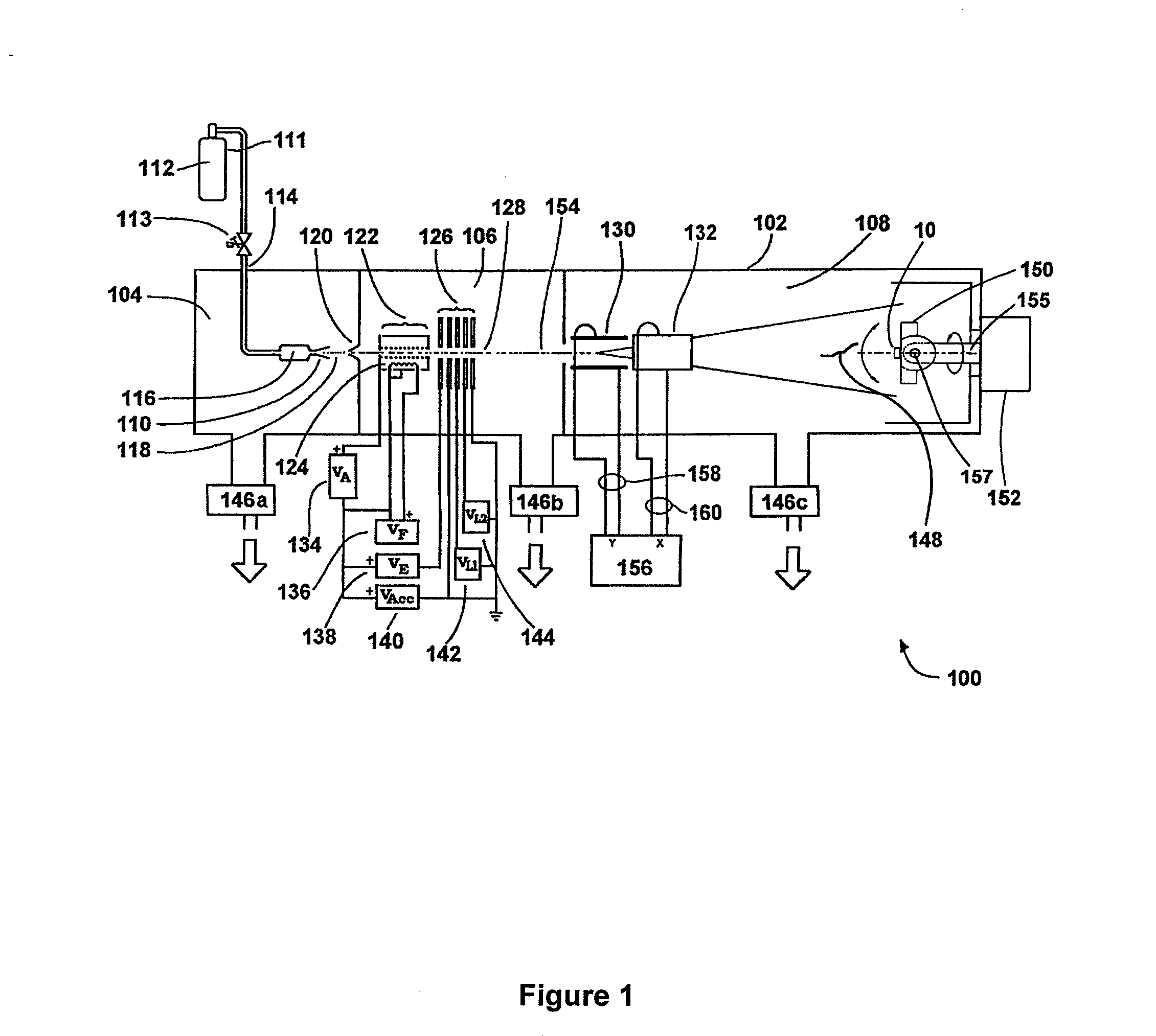
[0063]FIG. 9 is a schematic view of one configuration of a GCIB processing system 900 including the improved gas-cluster-jet generator of the invention. The GCIB processing system 900 includes the portion of an improved gas-cluster-jet generator shown in FIGS. 7 and 8. Referring again to FIG. 9, a first control shaft 902 connects with the first steering shaft 710 via first control shaft coupler 716. First control shaft 902 passes through a first rotary motion vacuum feedthrough 904 and has attached a first control shaft adjustment knob 906 for adjusting the longitudinal motion of first steering shaft 710 to control the alignment of nozzle 210 (and thus the gas-cluster-jet trajectory 218) with respect to gas skimmer 220 and other downstream beamline components. Like (not visible in this view) elements connected with second steering shaft 810 (not visible in this view) provide for adjusting the longitudinal motion of second steering shaft 810 and thus for controlling the alignment of ...


PUM


Abstract

A gas-cluster-jet generator with improved vacuum management techniques and apparatus is disclosed. The gas-cluster-jet generator comprises a substantially conically shaped vacuum chamber for housing the nozzle and jet exit portions of the gas-cluster-jet generator. A skimmer may be located at the narrow end of the conical chamber and a close-coupled vacuum pump is located at the wide end of the conical chamber. Support members for the nozzle are high conductivity “spider” supports that provide support rigidity while minimizing gas flow obstruction for high pumping speed. The conically shaped vacuum chamber redirects un-clustered gas in a direction opposite the direction of the gas-cluster-jet for efficient evacuation of the un-clustered gas. The nozzle and a skimmer may have fixed precision relative alignment, or may optionally have a nozzle aiming adjustment feature for aligning the gas-cluster-jet with the skimmer and downstream beamline components. Also disclosed are various configurations of gas-cluster ion-beam processing tools employing the improved gas-cluster-jet generator.

Description

CROSS REFERENCE TO RELATED APPLICATIONS[0001]This application claims priority from U.S. Provisional Patent Application Ser. No. 61 / 221,720, filed Jun. 30, 2009 and incorporated herein by reference in its entirety for all purposes.FIELD OF THE INVENTION[0002]This invention relates generally to cluster jet formation and the use of an improved cluster-jet generator in a gas-cluster ion-beam apparatus for workpiece processing.BACKGROUND OF THE INVENTION[0003]Gas-cluster-jet nozzles are employed as a means of generating a neutral beam of gas-clusters for use in, for example, molecular beam epitaxy and gas-cluster ion-beam formation.[0004]Gas-cluster-jets are typically formed by ejecting a high-pressure (typically about 2 atmospheres or more) condensable source gas into a vacuum through a nozzle. Various nozzle forms have been employed, including conical, sonic, and Laval forms. In each case, as the high-pressure gas expands into the vacuum through the nozzle, adiabatic expansion occurs a...

Claims


Application Information

Patent Timeline
Patent Type & Authority Applications(United States)
IPC IPC(8): H05H3/02G21K5/00
CPCH01J37/08H01J37/301H01J2237/31H01J2237/0812H01J2237/083H01J2237/045
Inventor HARRISON, STANLEY
Owner EXOGENESIS CORP
Why Eureka
Try Eureka