Induction accelerating device and acceleration method of charged particle beam

a technology of induction acceleration and charged particle beam, which is applied in the direction of magnetic resonance accelerators, accelerators, electrical devices, etc., can solve the problems of increasing the construction cost of the accelerator, the loss of particles reducing the acceleration efficiency, and the inability to actually accelerate the charged particle beam by the induced voltage without loss of particles

Inactive Publication Date: 2011-06-30
HIGH ENERGY ACCELERATOR RESEARCH ORGANIZATION
View PDF4 Cites 4 Cited by
  • Summary
  • Abstract
  • Description
  • Claims
  • Application Information

AI Technical Summary

Benefits of technology

[0050]Third, the present invention provides an accelerator 26 for accelerating arbitrary charged particles up to an arbitrary energy level, characterized by including: an injection device 29 including an ion source 30 that generates charged particles, a preinjector 31 that accelerates the charged particles up to a certain energy level, and an injector 32 that injects a charged particle beam accelerated by the preinjector 31 into an annular vacuum duct 2a having a design orbit 2 therein; an induction synchrotron 27 including a bending magnet 4 that is provided on a curved portion of the design orbit 2 and ensures the design orbit 2 of the charged particle beam (a bunch 3), a focusing electromagnet 28 that is provided on a linear portion of the design orbit 2 and ensures strong focusing of the charged particle beam, a bunch monitor 9 that is provided in the vacuum duct 2a and detects passage of the charged particle beam, and an induction accelerating device 5 connected to the vacuum duct 2a for controlling acceleration of the charged particle beam; and an extraction device 33 including an extractor 34 that extracts the charged particle beam accelerated up to a predetermined energy level by the induction synchrotron 27 to a beam utility line 35, and a transport pipe 34a, wherein the induction accelerating device 5 includes: an induction accelerating cell 6 that applies an induced voltage 8; a switching power supply 5b that supplies a pulse voltage 6f to the induction accelerating cell 6 via a transmission line 5a and drives the induction accelerating cell 6; a DC power supply 5c that supplies electric power to the switching power supply 5b; and an intelligent control device 7 including a pattern generator 13 that generates a gate signal pattern 13a for controlling on / off the switching power supply 5b, and a digital signal processing device 12 that controls on / off a gate master signal 12a that becomes the basis of the gate signal pattern 13a, a plurality of the induction accelerating cells 6 being provided according to functions, wherein the digital signal processing device 12 includes: a variable delay time calculator 20 that stores a required variable delay time pattern 14b corresponding to an ideal variable delay time pattern 14a calculated on the basis of magnetic field excitation patterns 15 and 24, and generates a variable delay time signal 20a on the basis of the required variable delay time pattern 14b; a variable delay time generator 21 that receives a passage signal 9a that is passage information of the bunch 3 from the bunch monitor 9 placed on the design orbit 2 along which a charged particle beam circulates and the variable delay time signal 20a from the variable delay time calculator 20 to generate a pulse 21a corresponding to a variable delay time 14; an induced voltage arithmetic unit 22 that stores an equivalent acceleration voltage value pattern 18j corresponding to an ideal acceleration voltage value pattern 18f calculated on the basis of the magnetic field excitation patterns 15 and 24, and receives the pulse 21a corresponding to the variable delay time 14 from the variable delay time generator 21 to generate a pulse 22a for controlling on / off the induced voltage 8; and a gate master signal output device 23 that receives the pulse 22a from the induced voltage arithmetic unit 22 to generate the gate master signal 12a that is a pulse suitable for the pattern generator 13, and outputs the gate master signal 12a after a lapse of the variable delay time 14, and the induction accelerating device 5 controls generation timing of the induced voltage 8, and wherein the preinjector 31 is an electrostatic accelerator, a linear induction accelerator, or a small-sized cyclotron.
[0051]Alternatively, the variable delay time calculator 20 calculates the variable delay time 14 in real time on the basis of a beam deflection magnetic field strength signal 4b for indicating magnetic field strength of the bending magnet 4 that constitutes the synchrotron 1, and a revolution frequency of the charged particle beam on the design orbit 2, and generates the variable delay time signal 20a on the basis of the variable delay time 14.
[0052]Alternatively, the induced voltage arithmetic unit 22 calculates an acceleration voltage value 18c in real time on the basis of the beam deflection magnetic field strength signal 4b for indicating the magnetic field strength of the bending magnet 4 that constitutes the synchrotron 1, receives the pulse 21a corresponding to the variable delay time 14 from the variable delay time generator 21 to generate the pulse 22a for controlling on / off an induced voltage for acceleration 18.

Problems solved by technology

In the acceleration of the charged particles, the loss of the particles reduces acceleration efficiency, and also causes a significant problem of activation of a spot of the collision with the wall surface of the vacuum duct to no small extent because any charged particles have high energy.
Thus, the charged particle beam cannot be actually accelerated by the induced voltage without controlling the synchrotron oscillation frequency.
Thus, each of the induced voltages needs to be controlled, which is complicated.
Also, the combinations of the induction accelerating cells having respective functions and the devices for controlling the generation timing of the induced voltages applied by the induction accelerating cells need to be prepared, which increases construction costs of the accelerator.

Method used


Image

  • Induction accelerating device and acceleration method of charged particle beam
  • Induction accelerating device and acceleration method of charged particle beam
  • Induction accelerating device and acceleration method of charged particle beam

Examples


Embodiment Construction

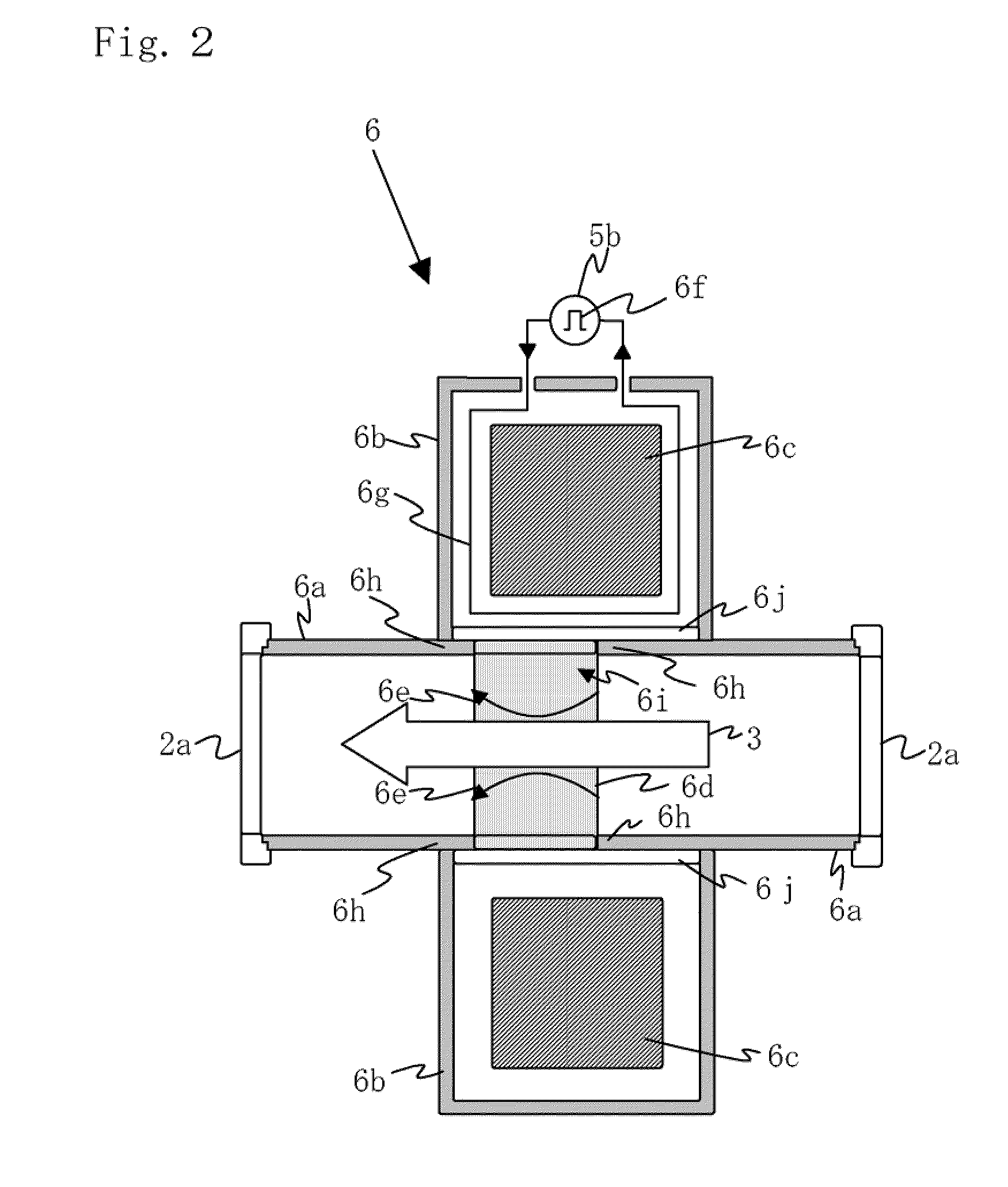
[0071]An acceleration method of a charged particle beam of a synchrotron 1 is achieved characterized in that the method includes the steps of: controlling generation timing of induced voltages 8 including a positive induced voltage 8a and a negative induced voltage 8b applied from a set of induction accelerating device 5; intermittently applying the induced voltages; and thus temporally separating functions of a barrier voltage 17 for confinement of a charged particle beam in an advancing axis direction 3a and an induced voltage for acceleration 18 for accelerating the charged particle beam.

[0072]Now, an induction accelerating device and a control method thereof according to the present invention will be described in detail with reference to the accompanying drawings.

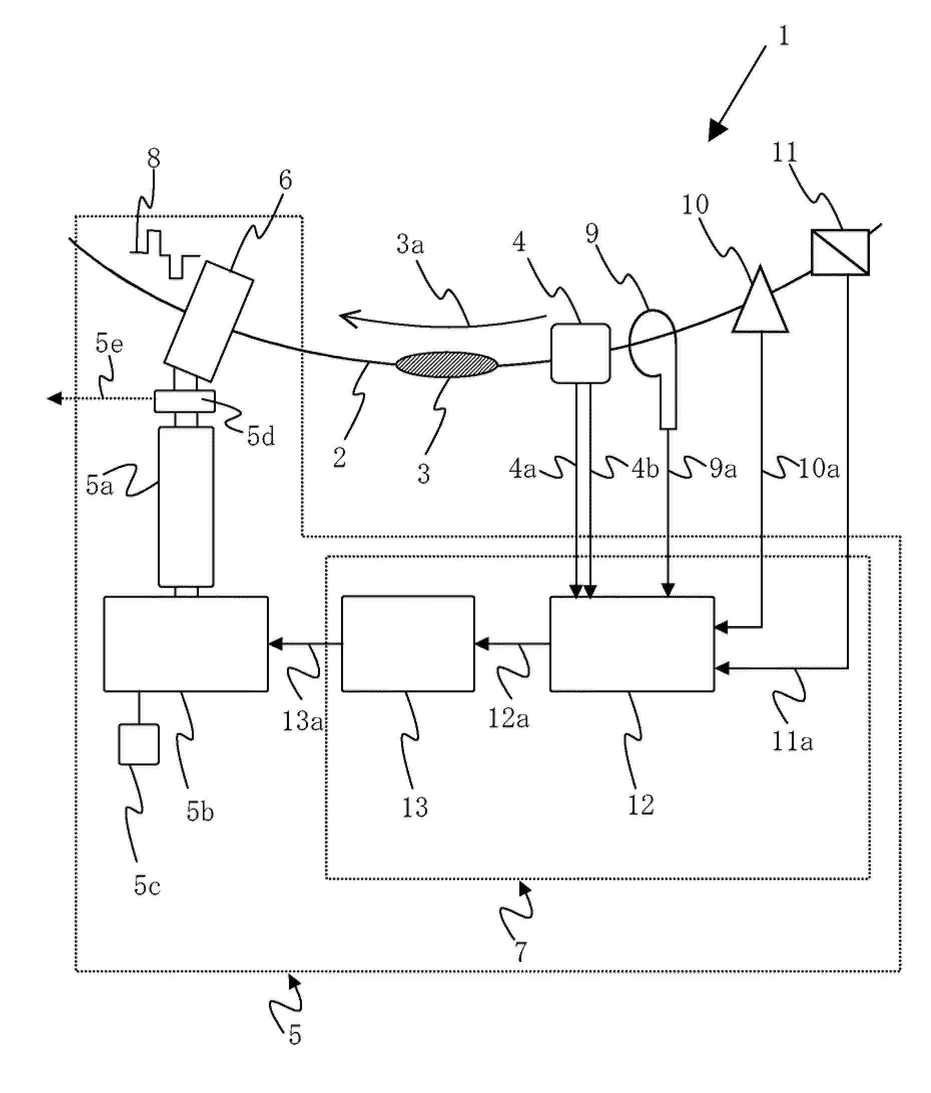
[0073]FIG. 1 is a schematic view of a synchrotron using an induction accelerating cell including an induction accelerating device according to the present invention.

[0074]The synchrotron 1 using the induction accelerati...


PUM


Abstract

The present invention provides a set of induction accelerating cell for controlling acceleration of a charged particle beam and an induction accelerating device for controlling generation timing of an induced voltage applied by the induction accelerating cell in a synchrotron. The induction accelerating device in a synchrotron includes: an induction accelerating cell that applies an induced voltage; a switching power supply that supplies a pulse voltage to the induction accelerating cell via a transmission line and drives said induction accelerating cell; a DC power supply that supplies electric power to the switching power supply; and an intelligent control device including a pattern generator that generates a gate signal pattern for controlling on/off the switching power supply, and a digital signal processing device that controls on/off a gate master signal that becomes the basis of the gate signal pattern.

Description

TECHNICAL FIELD[0001]The present invention relates to an induction accelerating device that controls generation timing of an induced voltage applied from an induction accelerating cell and allows acceleration of a charged particle beam in a synchrotron using the induction accelerating cell, and an acceleration method of a charged particle beam.BACKGROUND ART[0002]Charged particles collectively refer to “particles with charges” such as ions that are certain elements in the periodic table in a certain positive or negative charge state, and electrons. Further, the charged particles include particles consisting of a large number of molecules such as compounds or protein.[0003]Synchrotrons include rf synchrotrons and synchrotrons using an induction accelerating cell. An rf synchrotron is a circular accelerator for applying, with an rf acceleration cavity, an rf acceleration voltage synchronized with a magnetic field excitation pattern of a bending magnet that ensures strong focusing of a...

Claims


Application Information

Patent Timeline
Patent Type & Authority Applications(United States)
IPC IPC(8): H05H15/00
CPCH05H13/04
Inventor TAKAYAMA, KENTORIKAI, KOTAARAKIDA, YOSHIOSHIMOSAKI, YOSHITO
Owner HIGH ENERGY ACCELERATOR RESEARCH ORGANIZATION
Why Eureka
Try Eureka